 Jason Cho
I am currently a little bit obsessed with making the construction as simple as possible.
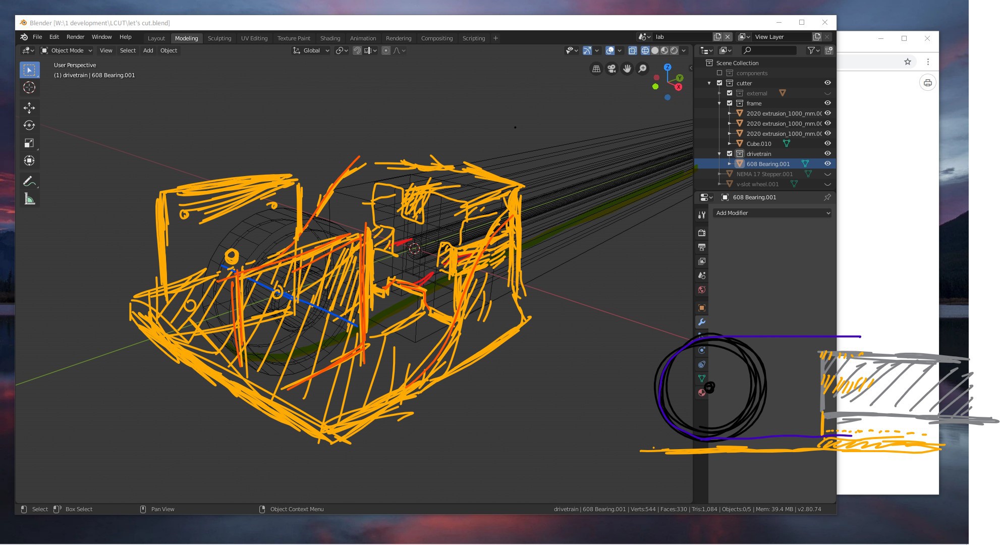
I figured to draw up some sketches and plan out how the parts and functions will be like.
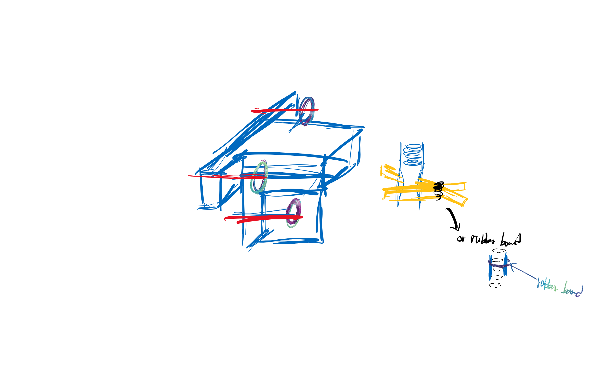
This is the sketch for the corner bracket(???) thing at the four corners, used to pin down the extrusion into a frame as well as supporting the GT2 idler wheel or pulley (attached with NEMA 17 steppers).
The drawing quality is obviously not that good, and I forgot to include a hole for the GT2 belt to move through. More on this later.
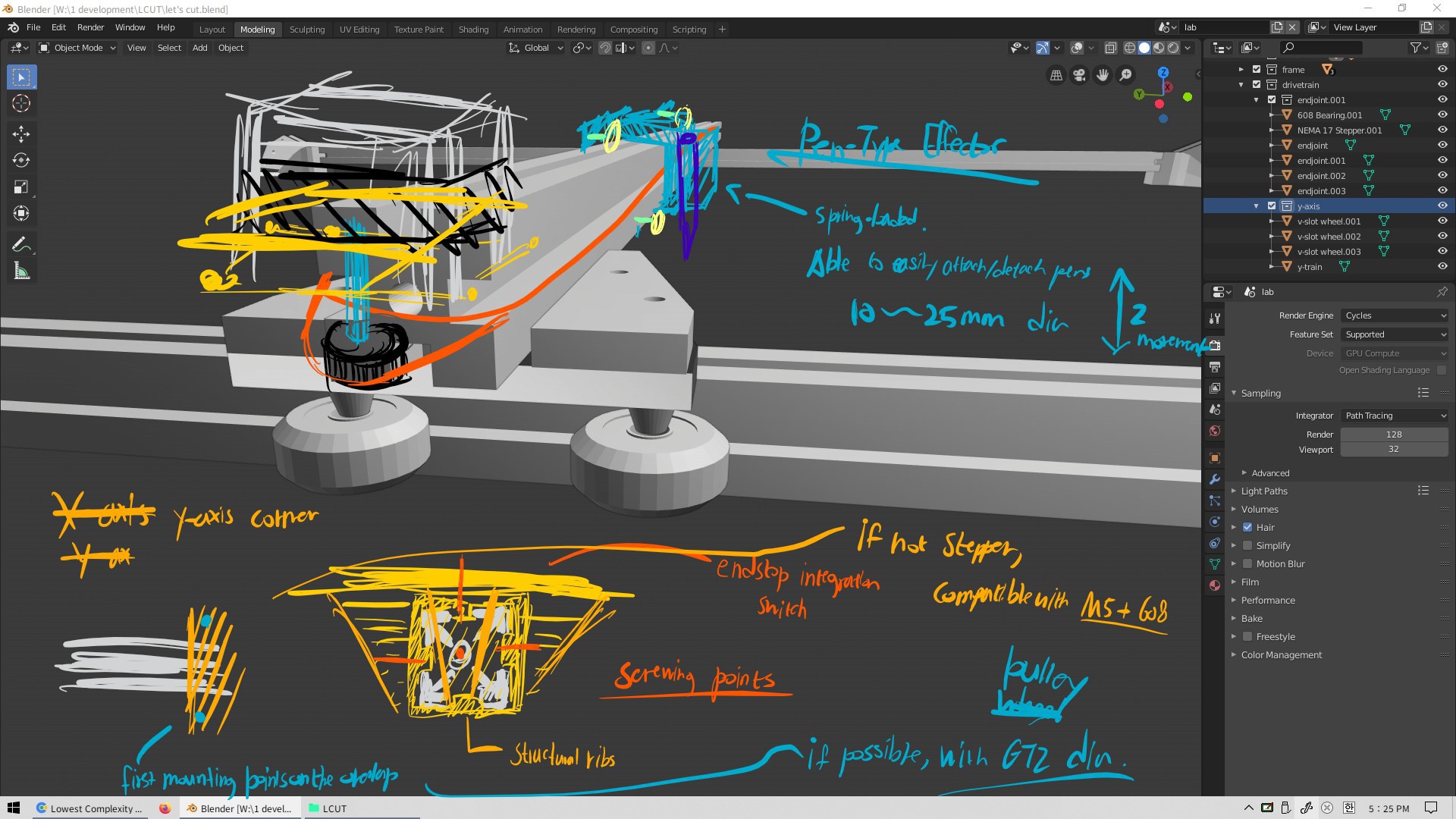
This is the brainstorming sheet to see how the y-axis (second layer axis? with one rail instead of two) end brackets as well as the effector would look like.
This is a very bad sketch for the end effector. As you would notice, it's called a pen effector. It's going to hold a pen.
I was inspired by the ODrive demo video drawing the cool pattern, and I think there would be lots of things I could achieve with a pen and paper, especially in school with my math and science teachers.
Some ideas are:
- Drawing mathematical curves (maybe fractals)
- Drawing big graphs, just for fun
- Holding a laser pointer for cool long-exposure shots (long exposure drawings)
Discussions
Become a Hackaday.io Member
Create an account to leave a comment. Already have an account? Log In.