Last time, we've got covered the method for sampling using diodes. However, that's only the beginning of sampling. Then you need to sample into something and then use it for something. Of course, it has to be a capacitor or something capacitor-like. This means you can sample into capacitor, gate of field-effect transistor, input of unipolar op-amp etc. I already mentioned the Houten's sampling head, which uses input of TL072 as sampling capacitor. However, its capacity is about 15 pF. This would heavily load the sampling bridge and also the input of the sampling head. Therefore the sampling head uses another 1 pF capacitor in series with the op-amp, which forms a capacitive divider and also limits loading the sampling bridge.
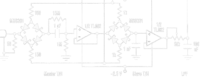
There is a reason why use a unipolar amplifier. You have to store the sampled voltage, but that's only one part of the job. After storing the voltage, you want to read it, probably. Well, unless you are Schrödinger's relative and don't actually want to know the voltage. Speaking of Schrödinger, that is the problem. Reading the voltage will probably somehow alter the sampled voltage. If you use bipolar amplifier after the sampling circuit, you will experience an effect called droop. Because a bipolar amplifier has a significant input current (remember, the sampling capacitor is only a few picoFarads), the sampling capacitor gets gradually charged (or discharged). If the time between sampling the voltage and measurement is always the same, you will obtain the data DC shifted, downscaled or mix of both. If the time between those events is not constant, the data will look as if they were noisy. The noise is approximately equal to the droop rate multiplied by the jitter of the time between sampling and measurement (if the droop is approximately linear).
Therefore there are two things you want to avoid. Input current of amplifier after the sampling circuit should ideally be zero and the time between sampling and measurement of the sampled voltage should be constant. And as short as possible.
This leads us back to the unipolar amplifiers. These have almost no input current, or at least negligible if the time between sampling and measurement is short enough. You can use MOSFETs, most JFETs, MOSFETs and most unipolar op-amps. However, avoid HEMTs, even if they are called field effect, since their input current is almost the same as in bipolar transistors. Or at least this applies to those which have a proper datasheet (many have only a few limiting values and a set of S-parameters).
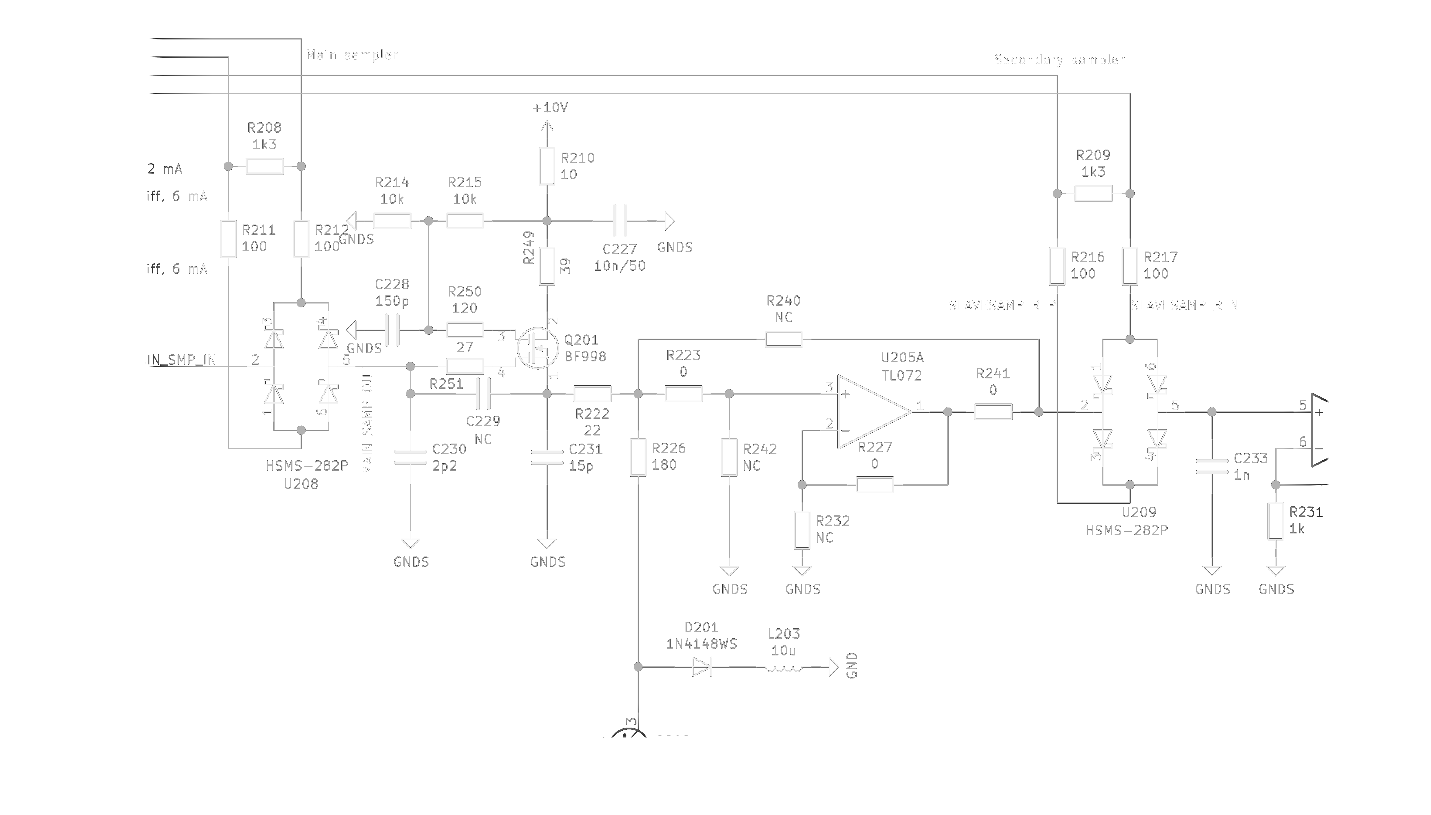
To fight with droop, my reflectometer uses BF998 MOS tetrode as input amplifier followed by second sampler section with much larger sampling capacitor (1 nF). These two samplers are precisely synchronised. The output of the second sampler is then measured by ADC. There is one slight error, the C231 in source of the tetrode is not used in the final reflectometer. It would make the amplifier unstable or make it oscillate. The same would happen if the C230 was larger, R251 was smaller and so on. The circuit is tuned to be as fast as possible while being stable. Making the C230 larger also loads the sampling bridge much more and causes the input impedance of the instrument drop at higher frequencies. Since the bonding wires of the sampling bridge are inductive, the sampling bridge forms a resonator with the C230.
To explain why there are so many resistors and capacitors placed in seemingly strange places, have a look at the transfer function of the amplifier. Please note that the -6 dB corner frequency is predicted by simulation to be at about 4 GHz, while the transistor is recommended for applications under 1 GHz. Yes, it smells of some positive feedback. But carefully crafted not to turn into instability. Sorry for the captions in graph being in Czech, the bright trace is S21 parameter.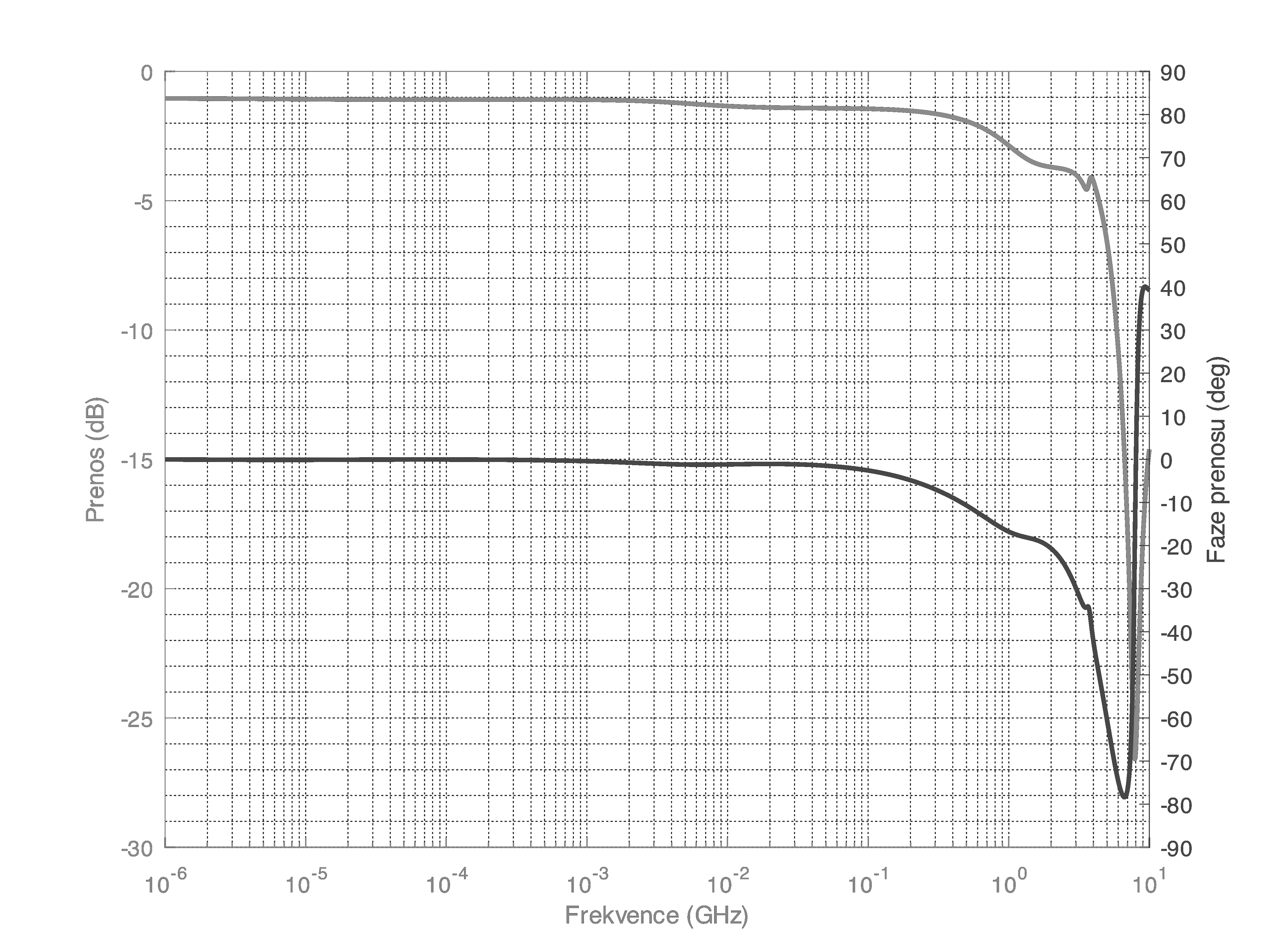
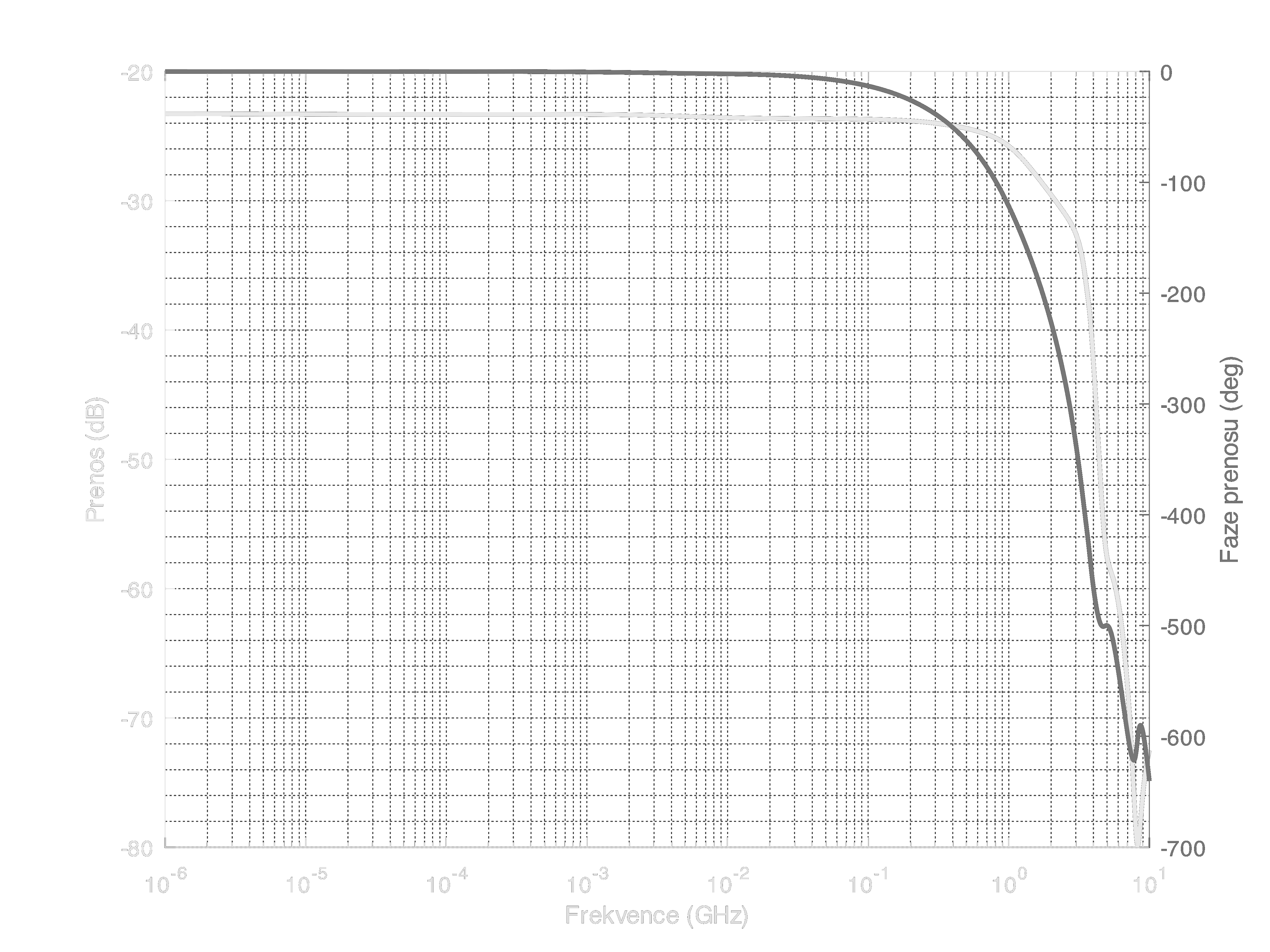
The transfer function of the whole sampler, from test connector to the output of the BF998 should look somewhat like the next image. According to simulations, the -6 dB corner frequency should be near 2 GHz. To repeat a currently common cliché, "not good not terrible". If you want more bandwidth, you have to come up with a better strobe driver than a LVCMOS outputs with series resistors, for example one of those Tektronix ones from previous log. And a better buffer amplifier. However note that these graphs are from simulation which was performed for the case when the sampler is in the "track" mode. In reality, it is possible to measure faster risetime than predicted by these graphs, because the graphs do not take into account the characteristics of the sampler during the transition to "hold" state and the behaviour of the circuits after that event. Of course, it could be worse as well in reality.
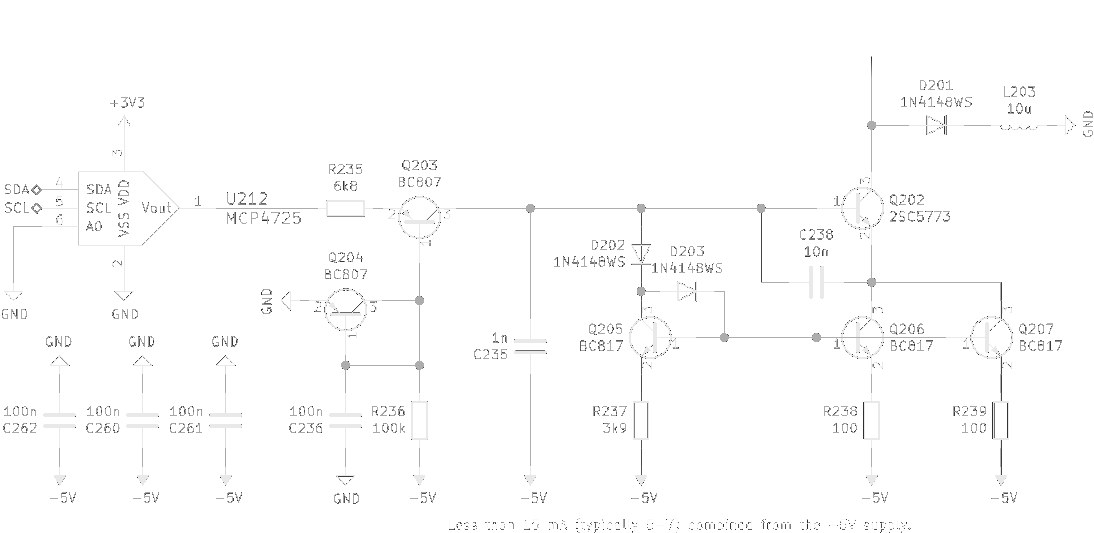
To reduce distortion and increase input impedance of the BF998, a current source is used in its source terminal. The current can be set from 0 to about 12 mA using the DAC. This facility is used for autocalibration of the amplifier, because the BF998 has large manufacturing tolerances, so this cicuitry allows to tune the DC offset of the measurements.
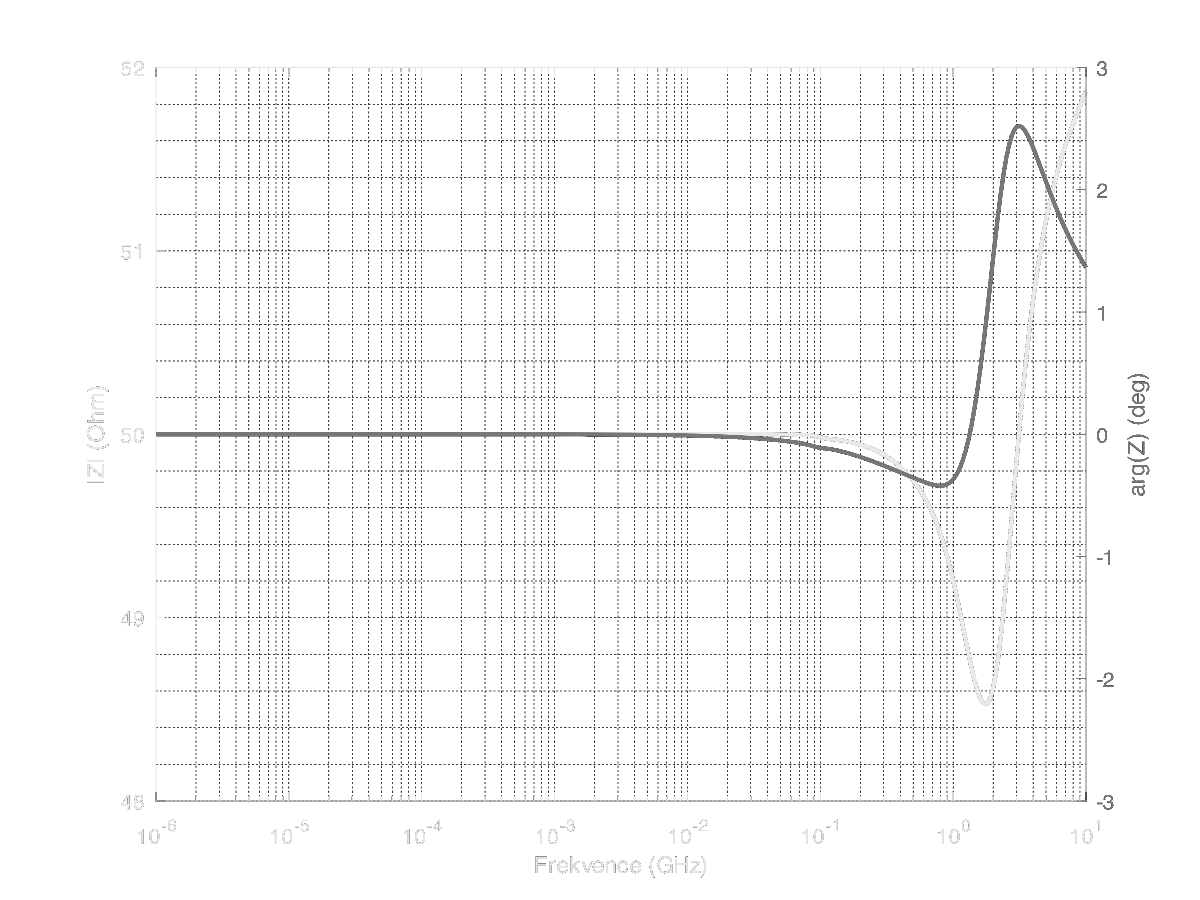
If you are curious about the input impedance of the instrument, you can find it on the next graph.
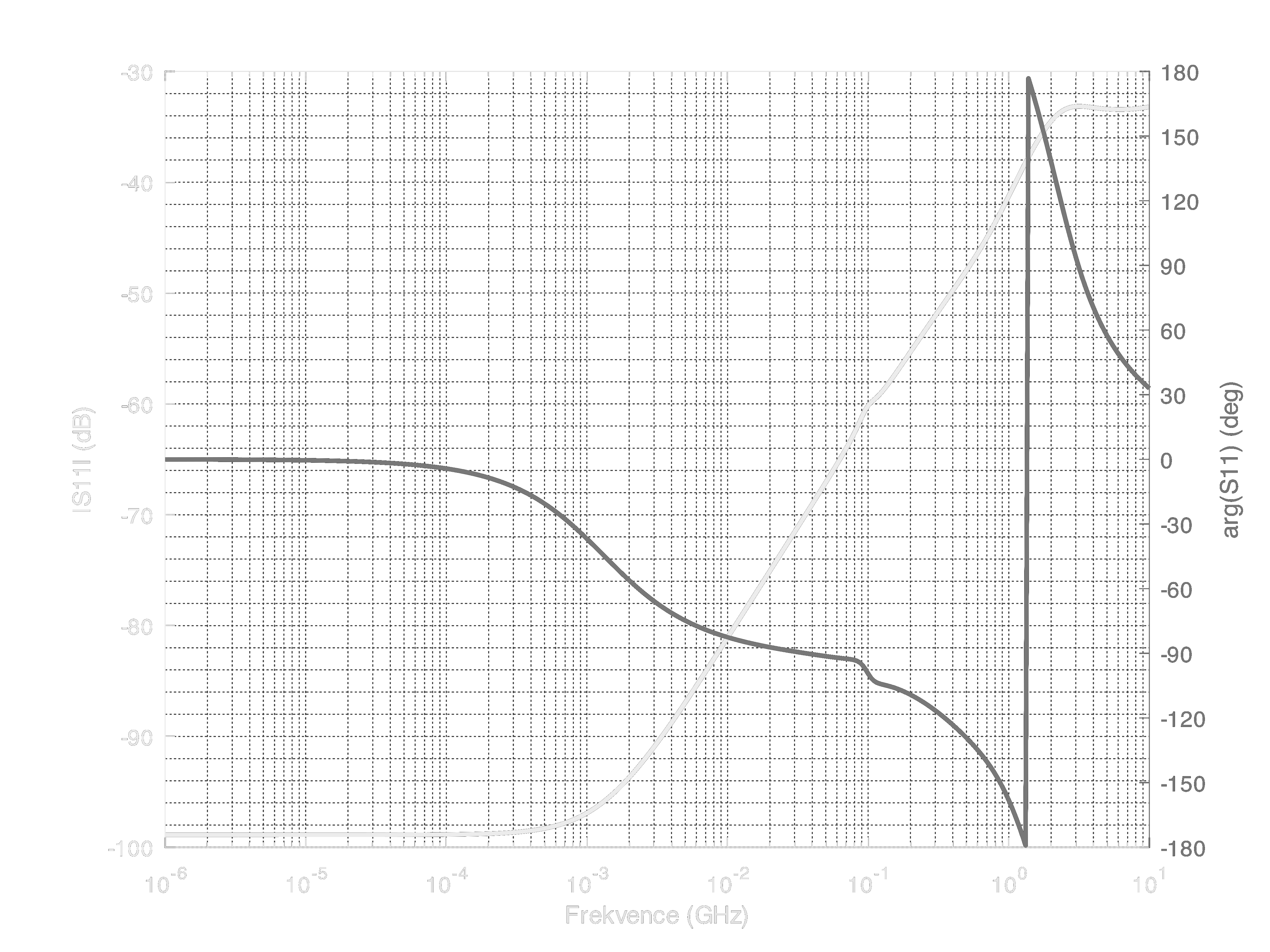
If you would like more to see the input reflection coefficient, the next graph could suit your curiosity. Of course, it is only hypothetical and based on simulation. You can see the resonance of the sampling bridge between 1 and 2 GHz.
Next time, I will probably write about the pulse generator.
 MS-BOSS
Discussions
Become a Hackaday.io Member
Create an account to leave a comment. Already have an account? Log In.