 Bud Bennett
I wanted to see how well this probe would perform in its intended application. I took the case off my old Macintosh 512k and measured a few waveforms. Here's the power supply schematic:
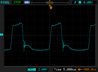
The primary side of this SMPS power supply is not isolated from the 125VAC mains. All of the circuitry to the left of the multi-tapped transformer are moving up and down 180V at 60Hz with respect to the ground reference on the right side. There are a lot of voltage swings that exceed the probe's ability (±25V), but you can get a pretty good idea about what is going on by measuring lower voltages. The first point that I measured was from node "5", the base of Q11, to the virtual ground at the base of Q9. It looks pretty much as it should.
Then I put the probe leads from node "3" to the virtual ground. Again, as expected.
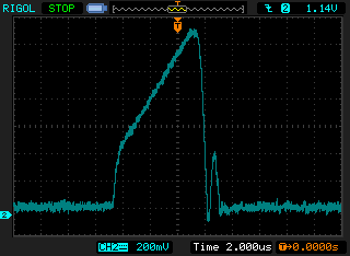
The last node that I probed was the gate of Q10 w.r.t the virtual ground. This is a lot uglier, but seems appropriate.
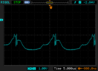
There is an artifact from the large common mode voltage. I recorded this to show the amount of bleed through from the common mode:
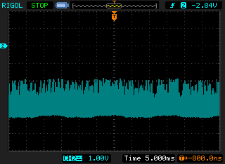
It is the same signal at the gate of Q10, but the baseline voltage shows the 60Hz common mode. It's on the order of 5mV (50mV @ 10X), so it is tolerable for this situation.
I'm pretty happy at this point. I wish that I had this capability when I was trying to figure out what was wrong with this circuit a few months ago.
Discussions
Become a Hackaday.io Member
Create an account to leave a comment. Already have an account? Log In.