Close
0%
0%

A Very Accurate LED Clock

This clock is accurate to +/- 1 sec/month without relying on GPS or NTP synchronization. The RTC is implemented in firmware.

Similar projects worth following
STM8S003 LED clock. This clock uses a firmware 24-bit Numerically Controller Oscillator for fine tuning tolerance. Once calibrated, it removes the need for external synchronization.

Features:
- 6 digits 7 segments LED display
- Accurate all firmware based RTC with Supercap for RTC backup.
- Time, date, leap year, Daylight Saving Time
- Low power consumption: 5V at 20mA

Motivation:

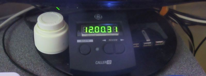
I sometime play games into the night without realizing how late it is. I need a clock below my monitor that is non-distracting, large, easy to read in my peripheral vision. Also it would be ideal if is set and forget i.e. accurate enough and handle silly DST time changes.
Additional pages for this project on HaD:

https://hackaday.io/page/6687-stm8-led-clock - more project details
https://hackaday.io/pages/10708 - test results

External Project page: 

Github: https://github.com/FPGA-Computer/LED-Clock

User interface

The clock and display time:
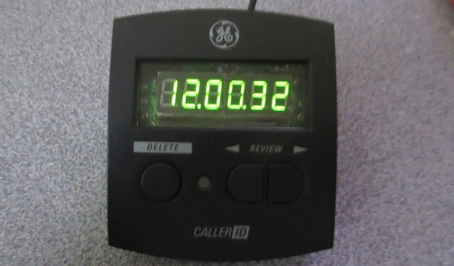
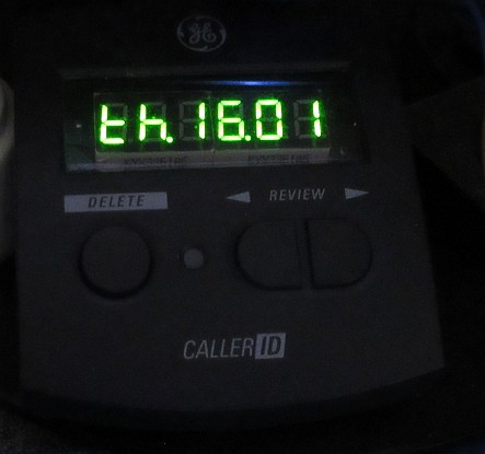
The arrows key switches between the time and date display.  The date display uses a different format to distinguish the modes.  The 7 segment LED can only show a limited set of characters and have to make do with some approximations. 

e.g. Th(ursday) 16 Jan is shown below.  
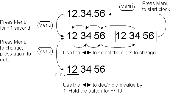
Time (and similarly date) can be set using 3 buttons.
Hardware description:

Instead of using the usual RTC modules used by other projects, the RTC is implemented in firmware with features such as Daylight Saving Time. The RTC code can be adapted for oddball clocks that uses different units of time. e.g. Metric time or Mars time. 

The clock doesn't require an ultra accurate crystal.  As long as it has a very stable frequency, then the tolerance can be calibrated out.  I used a common AT-cut 12MHz crystal as the frequency source. 

If clock is used in a home environment with temperature controlled, chances are that the temperature variation is small enough to get away without using a TXCO.  e.g. Heater set to 21C and air condition to 25C means that the variation is about 4C.

There is only a very narrow frequency range that you can shift a crystal by the load capacitance and a trimmer capacitor doesn't make fine adjustment predictable nor repeatable.

A 16-bit timer in the STM8 generates a 20Hz IRQ. A more accurate 10Hz is then generated from using a 24-bit Numerically-controlled oscillator (NCO) implemented in firmware.

e.g. if your 20Hz is  +50ppm fast = 20.001Hz, 10Hz can be generated by dividing it by 2.0001.

NCO can perform fractional frequency division by keeping track of the phase in an accumulator.  Don't let the name fool you, this 3 extra lines of code is all that's needed for very fine frequency adjustments!
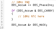
The 10Hz is used by the RTC code to update the time, date and implement the Daylight Saving Time (DST) for North America.

 (repost from https://hackaday.io/page/6687-stm8-led-clock)

I made a digital clock. Originally I planned to use a VFD, but the user interface on a 4 digits would be too limiting. I used a STM8S003, 74HC595 and a couple of  the cheap green 7 segment displays. The display efficiency is actually not bad as the entire clock runs on 5V at ~20mA.

The LED driver is on a separate rail. A supercap allows the STM8 to work for a few minutes during a power failure. 
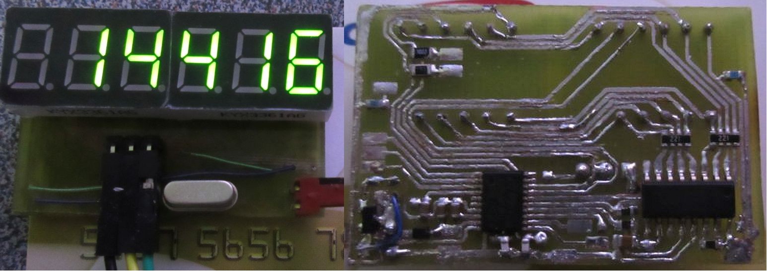
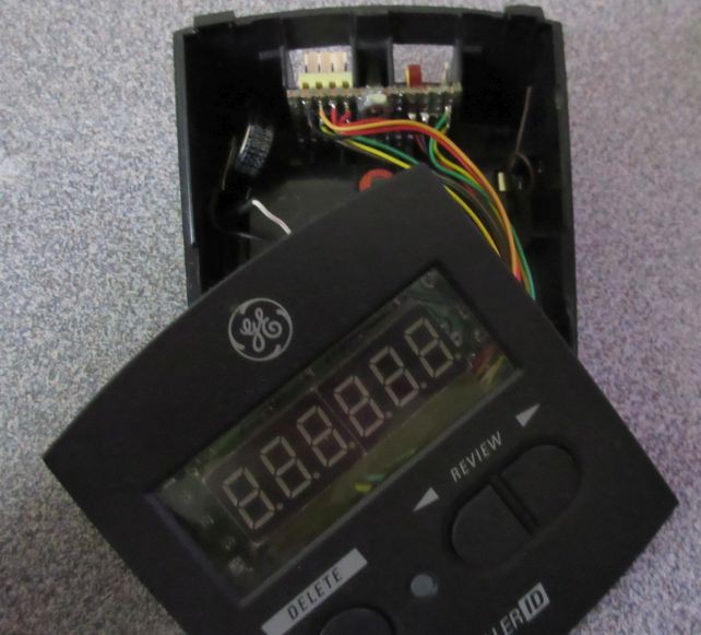
The PCB is wired to the original (stripped) Caller ID PCB to use existing buttons. The same GPIO for the common cathode driver when off-duty is used for polling the buttons.
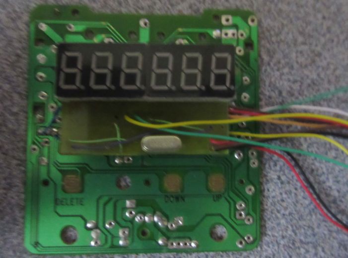
I could have used the STM8 alone to drive the display. By adding the 74HC595, I freed up a few GPIO lines for future expansion.
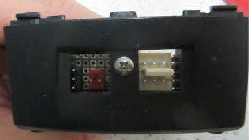
External I/O

UART, I2C, a Timer pin, 5V power and the hardware debug interface (SWIM) are connected to the headers on an I/O panel PCB using the existing RJ11 cutouts. I have since changed the power connector to a MicroUSB as it has much better latching.
Side by side view of the old traveler's Casio clock it is replacing as it...

Read more »

  • Backup battery

    K.C. Lee12/10/2021 at 17:15 0 comments

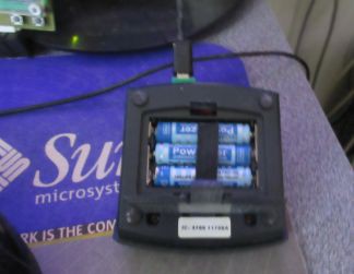
    Battery compartment of my digital clock (old Caller ID)

    The power in my apartment used to be very reliable, but things have deteriorated in the last 10 years or so.  I have experienced serval power outage and some up to 6-7 days.

    The Supercap I have is only good for a few minutes as the STM8 clock uses around 2mA to keep its firmware RTC working at the minimal state.  It requires a minimum of 3V, so Li coin cells are out. I don't quite trust Li-ion batteries enough to be trickle charge 24/7. 

    I use some old NiMH batteries.  They lost most of their capacity, but they are still good for a few mA load. They are sitting in a compartment at the bottom of the clock, so gravity would protect the electronics from any leaks.

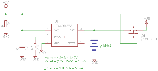
    Here is a battery backup for the digital clock. +5V is the power source (e.g. USB) that can go away and +UB is the backup rail.

    From Reddit:

    Can you replace a Ni-Cd backup battery by NiMH in a Tandy TRS-80 model 100?

    >So, NiCd's are super easy to charge. You just throw current into them at about 0.1C, and once they're full, they turn the rest into heat. Harmlessly, and forever. You can just slowly overcharge NiCd and it's fine with that. Lots of old two-way battery cradles did just that, and it's why the radios were always warm when you picked them up.

    >Do that to NiMH, and they "vent". NiMH needs charge termination, or needs to be floated at a lower voltage so it never gets quite "full". Right around 1.35 volts per cell seems happy.

    ------------------------------------------------------------------------------------

    You'll notice it a bit funny as the LTC4054ES5 is a Li-ion charger chip and I am using it for NiMH. It turns out that 3 NiMH has just around the same charge voltage as Li-ion battery.  

    The -ES5 part has a recharge threshold of -150mV, so it would starts charging the batteries when they drop to 1.35V each.  It charges the cells at 50mA to about 1.4V and stop charging when the charge current is below 5mA.  (The minimum charging current for this chip is 50mA.)  The actual cell voltages can be reached is slightly below 1.40V because of I*R drops due to their internal resistances.

    I use a P-MOSFET (Q1) as a switch for the back up rail to reduce the voltage drop vs a Schottky diode.

    This has been working for close to half a year now without any leaks.  It also survived a 24+ hour of back out with plenty of  juice left.

  • my thoughts

    K.C. Lee05/13/2020 at 11:34 0 comments

    Like a lot of my projects, I try to build things with what I have and reuse/repurpose some old broken parts for different purposes. I also try out new ideas which in this case is the use of NCO for trimming the clock.  Unlike the clock on website https://time.is/ my clock doesn't skip a second here and there.

    I have been coding RTC in firmware instead of relying a chip or a module or NTP or GPS like most clock projects. NTP and its etwork hardware and IP stack doesn't come for free either.  It means less parts for me to stock, order or pay for.

    I have read user comments about how inaccurate that some of the modules can be. My $0.20 microcontroller cost much less than a RTC and in most case can get close to the accuracy of the better parts after calibration. The calibration doesn't require anything other than my patience and a PC running a web browser. Since the calibration is done over a long time period, it averages out minor drifts due to temperature fluctuations etc.

    A RTC module has much lower standby power consumption than firmware running on a microconroller. For my projects, I do not see the need for long duration of standby operation.

    My 2nd year computer science course actually taught that as an example of a timer interrupt. Daylight saving time is implemented in my firmware. As we have seen how the politics can change the duration on a wimp rendering a hardware implementation non-functional.

    I always prefer a firmware trim than a mechanical trimpot or a trimmer cap as it is far more reproducible and controllable than trying to turn a fraction of a degree assuming you know which direction with a screw driver.  Thankfully some of the RTC chips and RTC peripherals on some of the microcontroller such as the STM32F030 are incorporating a trim register.

View all 2 project logs

Enjoy this project?

Share

Discussions

Dan Maloney wrote 01/16/2020 at 19:32 point

I too love an accurate clock, and this is pretty impressive. But one thing I'd pay dearly for more than accuracy is synchronization - I hate that the microwave clock and the range clock seem to be in time zones separated by a couple of seconds. The clock in my high school were all synchronized, and that was 40 years ago. You'd think we'd have figured this out by now.

</rant>

  Are you sure? yes | no

K.C. Lee wrote 01/16/2020 at 19:46 point

AC frequency has/had pretty good long term accuracy until the politicians in the US decided to mess with it.  

My store bough $10 LED clock is pretty accurate, but I had to add a capacitor because the active power factor on my PC PSU injects enough noise to mess it up.

This LED clock is around $2-3 worth of part (minus the repurposed case and supercap backup).  :) I think I can get $6 GPS modules.

I have serial port on the back of the clock for GPS, but reception at my computer desk is not good and I am too lazy to write code.  I thought about a IR broadcast from my PC, but it turns out that my computer clock is less accurate - I saw up to 3 second drift a day until it was corrected by Windows synchronizations.

  Are you sure? yes | no

Similar Projects

Does this project spark your interest?

Become a member to follow this project and never miss any updates