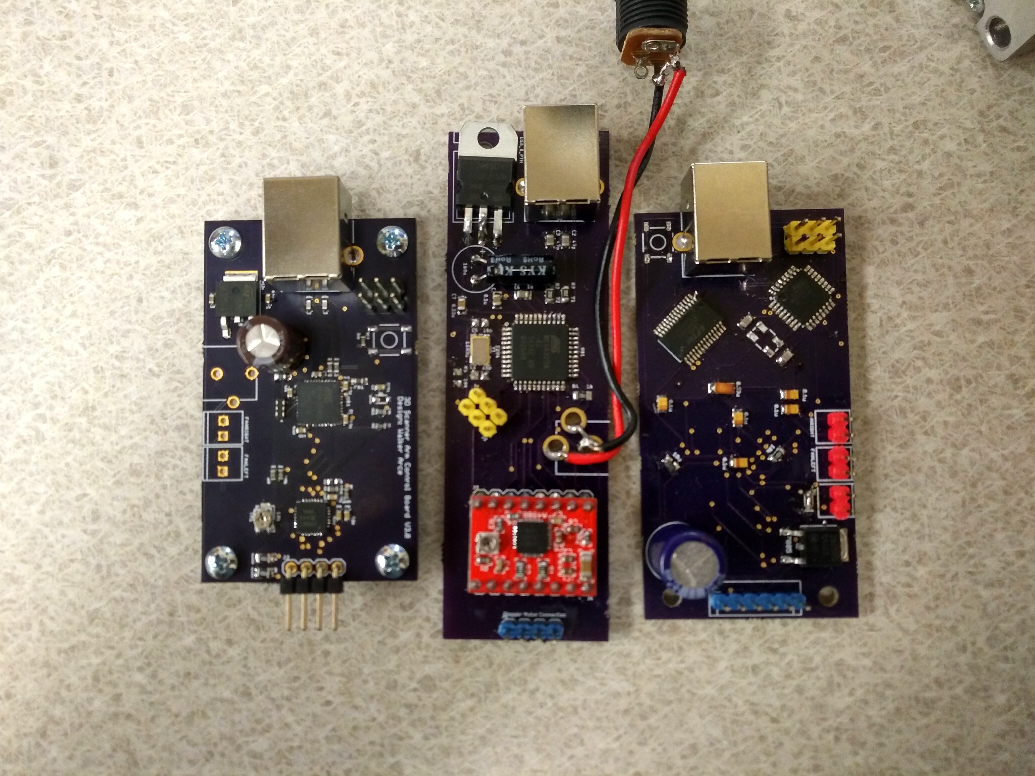
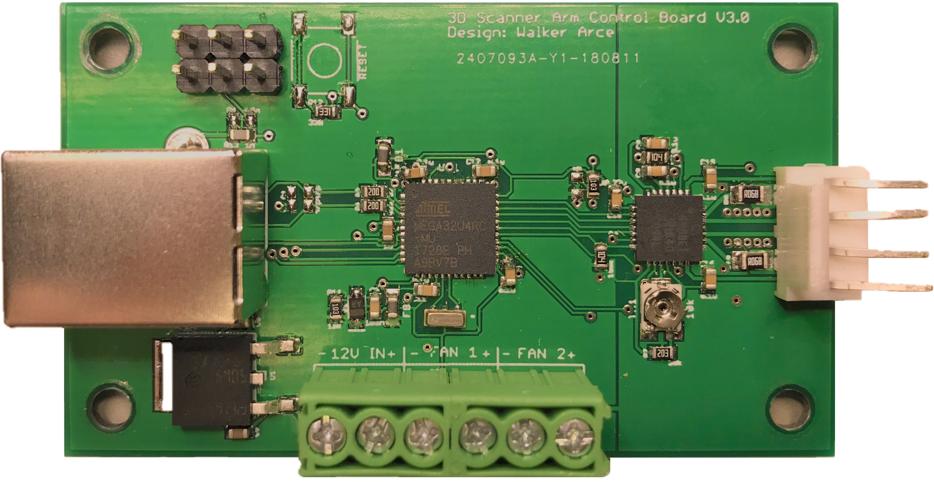
This project went through two years of work and ended up with a few previous iterations that each brought its own lesson. When I started this project I was a Sophomore in Electrical Engineering and had essentially started my dive into embedded electronic design.

From left to right is the timeline of iterations.
By the time it was over, I demonstrated a workable knowledge of electronic design, had learned lessons in thermal dissipation, and learned how to layout components with at least a general understanding of how it would fit into the final enclosure.

For instance, when debugging the board to the far right, I could not get the motor driver to operate unless I was putting pressure on it with my finger. Come to find out, it was immediately going into thermal runaway and shutting down. So, I sat down and spent time designing the thermal dissipation for the motor driver. I researched other designs, the physics of heat transfer in PCBs, and correctly utilized the suggested layout in the datasheet for the A4988. The result was an operational board that ran with low heat and was able to drive a NEMA 23 stepper motor around a circular path with very rare slippage all while having a 590 gram Sense 3D scanner on the end of the apparatus.
This project was put up to document this work since it was just sitting on my hard drive, so hopefully someone can make good use of it.
Discussions
Become a Hackaday.io Member
Create an account to leave a comment. Already have an account? Log In.