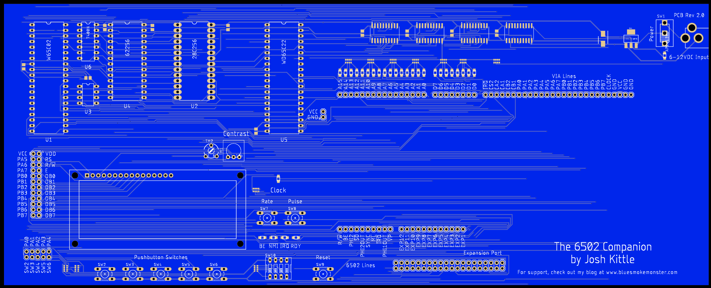
This board represents a major design shift - the move away from through hole components to SMD parts. The reason for this, really, is ease of assembly. This will still be a kit, but the only thing the builder will have to solder will be things like PCB sockets, the power switch, big stuff like that. Let the board house do the resistors, LEDs, logic ICs, etc. It just makes good sense, I think. The boards are currently in production (I timed things horribly in line with Chinese new year) so it might be a while before i get them back. I ditched the USB connector and decided to add a voltage regulator to make the input voltage a bit more flexible. Previous boards HAD to be 5vdc and nothing else. Here is what they should look like (minus the SMD components soldered on) when I get them

You'll notice that much has come full circle on the design. My eyes really like the way this layout has come together. I'll post some pics of the finished board when they arrive! And of course, testing....
I've been making a conscious effort to keep my design in line with the work Ben Eater has been doing lately - I think a lot of people who are working with his kit could have fun using his parts on this board - So a huge thanks to Ben for the work he's done on that front!
 Josh Kittle
Discussions
Become a Hackaday.io Member
Create an account to leave a comment. Already have an account? Log In.