 Ringo2k
Connections on the Arduino
- D4 = Encoder CLK input
- D3 = Encoder DT input
- D2 = Encoder switch input
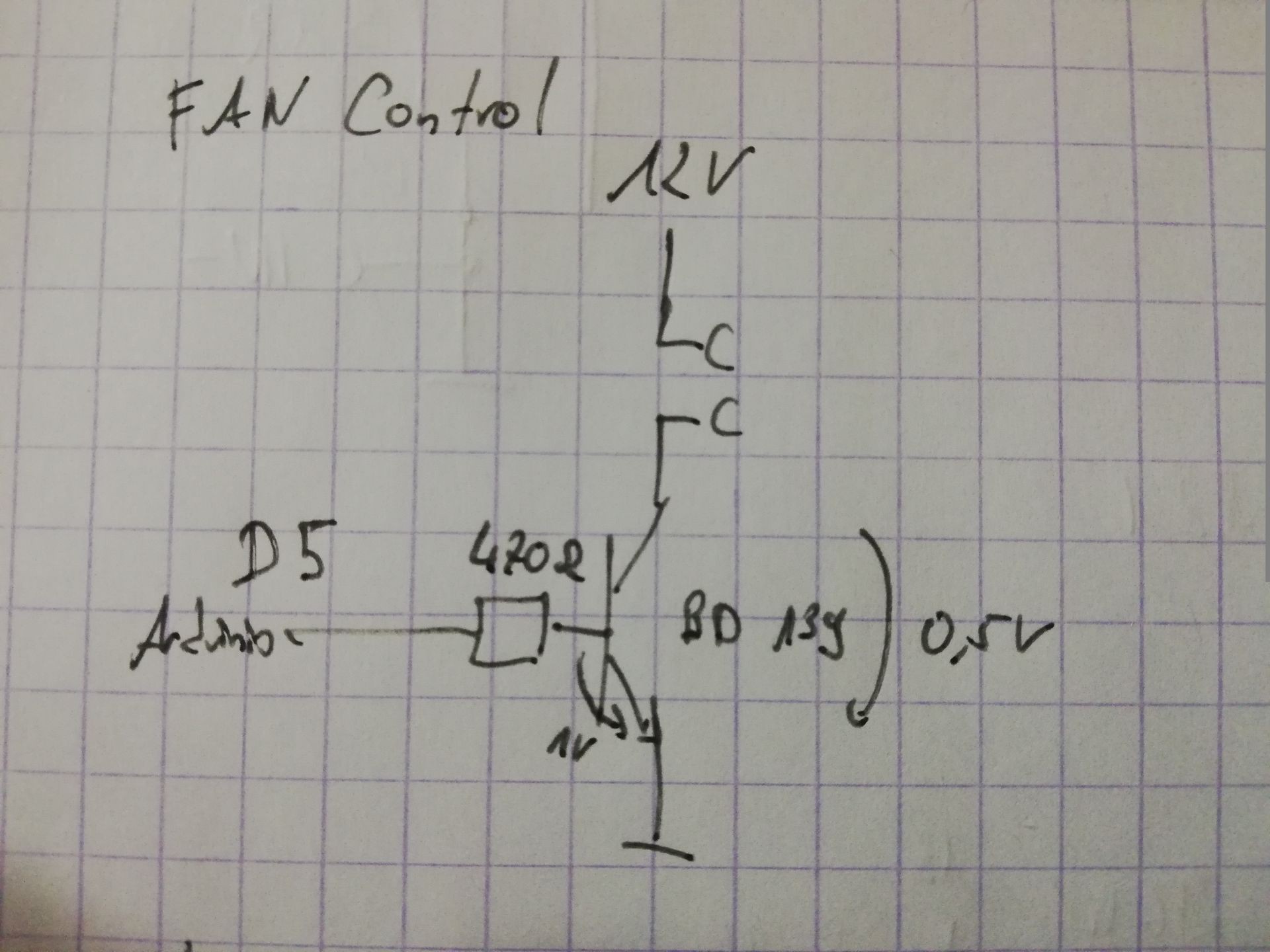
- D5 = PWM output for fan control
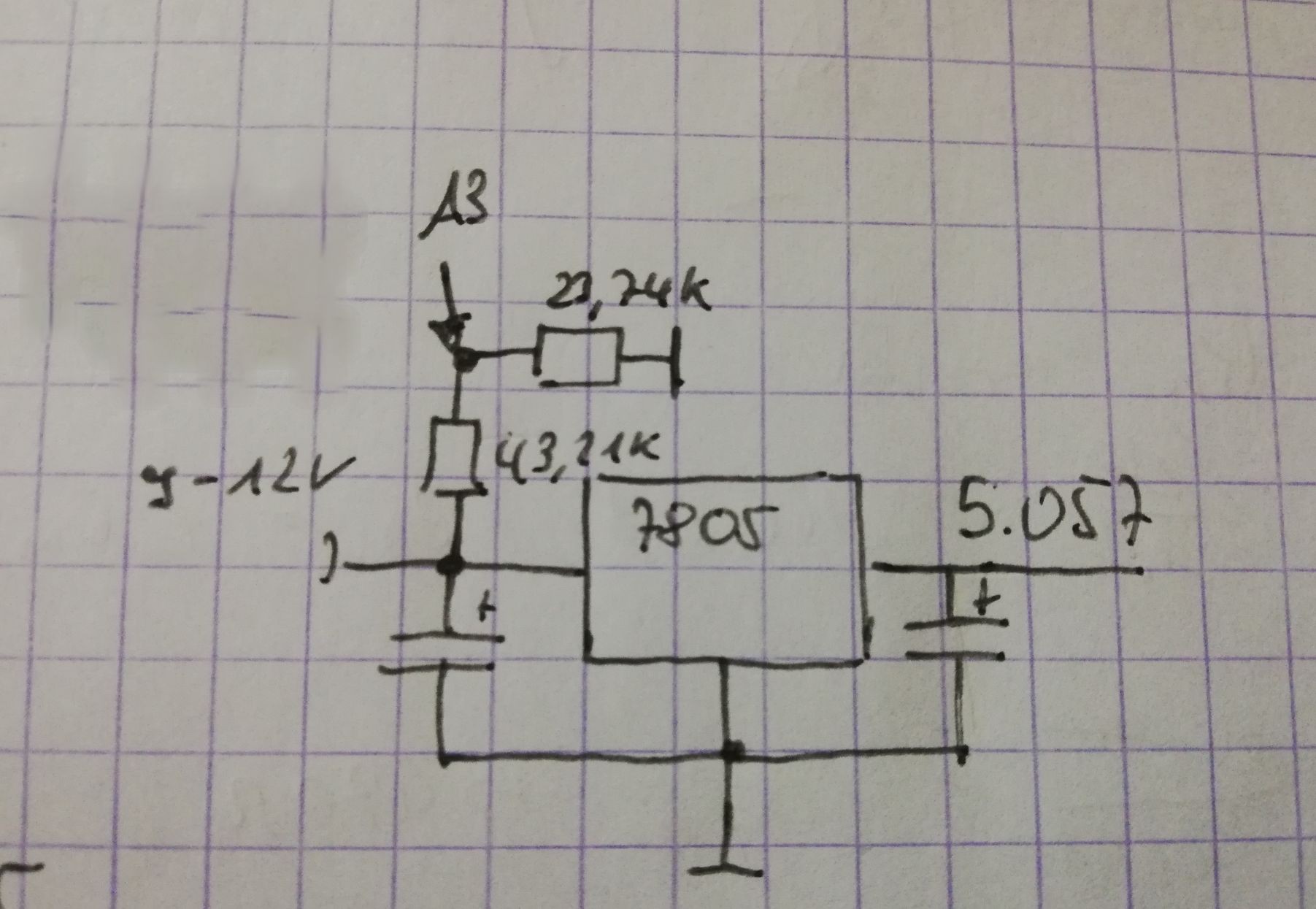
- A3 = Analogue input for power supply voltage
- A4 = I2C SDA
- A5 = I2C SCL
- A2 = Analogue input for input voltage (times 0.174)
- A6 = PTC on heatsink input
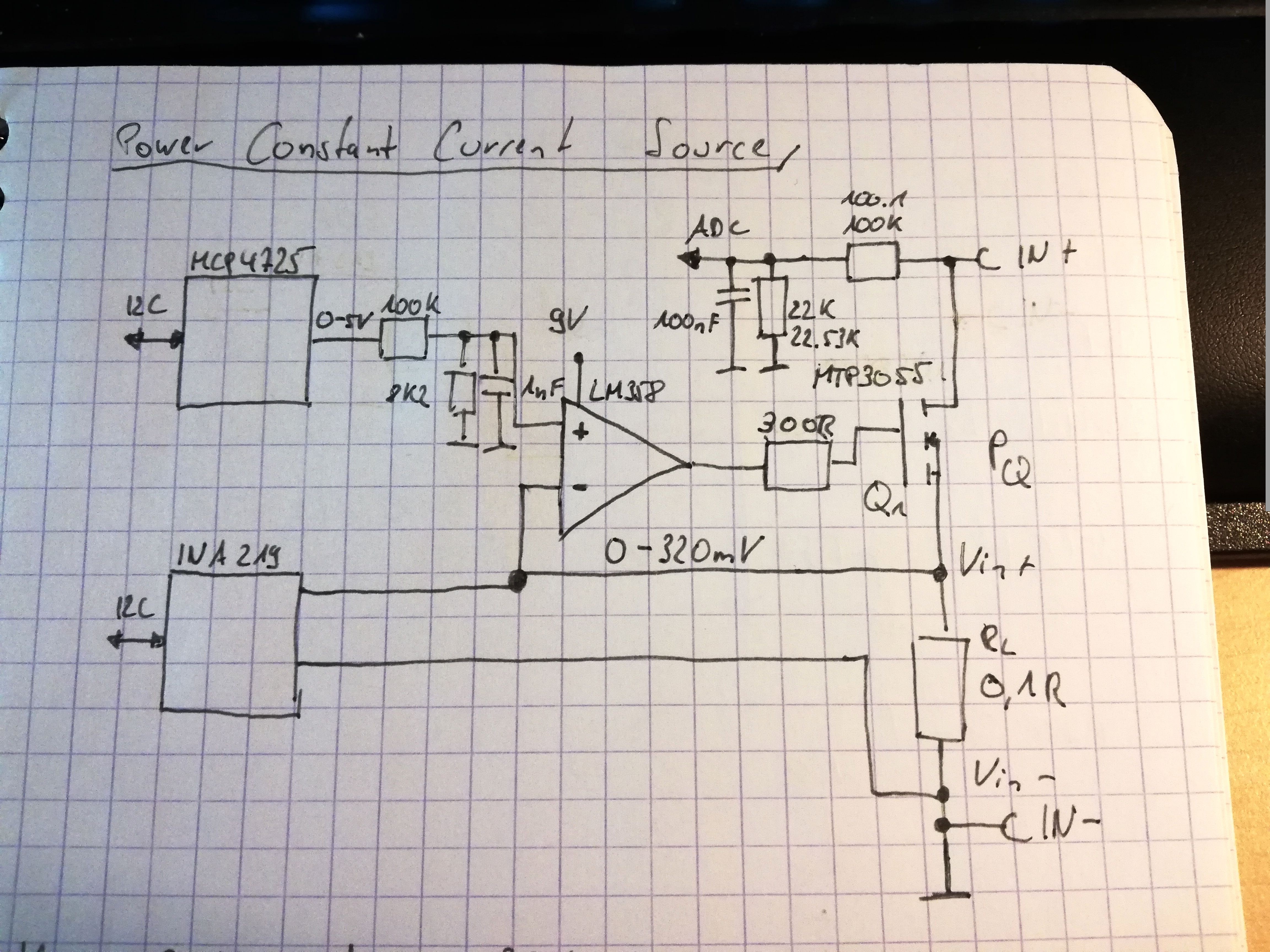
Analogue frontend
The MCP4725 is a DAC which is used to set the target current, therefore a simple constant current around the LM358 is used.
To measure the real current the INA219 I2C board is used. It has a 0.1R shunt resistor on board and can meassure current to 3.2A @ 30V or 96W :-)
This results in a shunt voltage of 0-320mV, the DAC provides 0-5V output. To fit it to the 0-320mV a voltage devider is used (100k to 8k2 = /13.2).
The input voltage of the device under test (DUT) can be 30V, will also be devided by 5.54 to get a range of 0-5V for the arduino to measure the input voltage.
After making some real measurements the formular to convert the DAC value into real current ist:
I = DACValue * 686µA
So the resolution is 686µA.
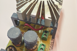
Heatsink
The heatsink is from pollin.de and has a fan for cooling, this fan can be controlled by the arduino with PWM. The heatsink has a PTC to get the heatsink temperature and make a fan regulation so the fan is not running full speed all the time, just when needed. Therefore a simple NPN transistor is used (BD139).
The PTC was from the drawer, it has about 1k by room temperature. So another 1k2 resistor is used to make a measurable voltage.
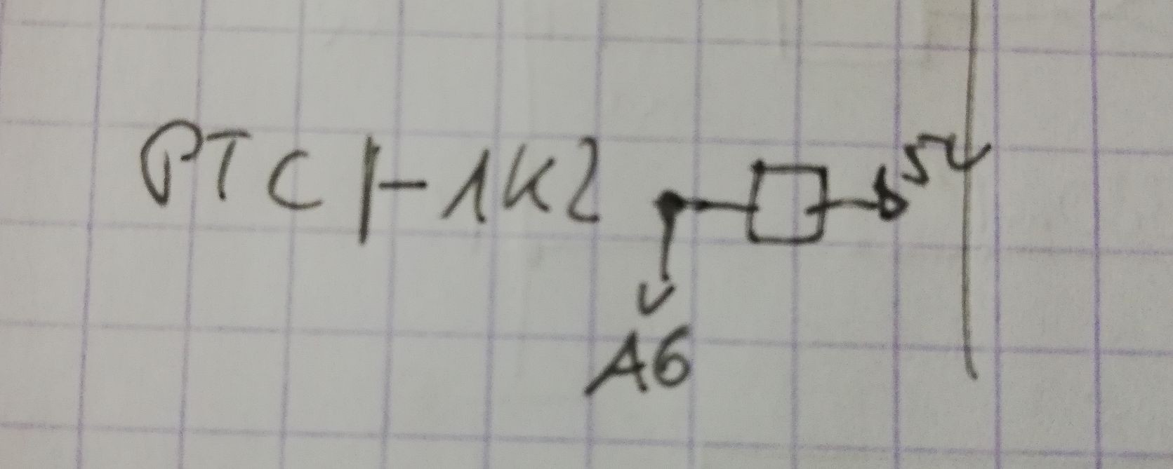
To get the heatsink temperature in Celcius a small calibration was made to get the factor for transforming the ADC value in temperature right.
So with a little bit of math the formular to get the degree value is, 838 is 0°C:
temperature = (838 - ADCValue) * 0.11
| Temperature | ADC |
| 23,3°C | 626 |
| 58,0°C | 316 |
| 43,3°C | 433 |
| 36,7°C | 495 |
Power Supply
The power supply will be a AC adaptor or can also be battery powered when needed. Because the arduino and the analogue frontend does not consume much power there is just a 7805 to make clean 5V. A voltage devider is used to measure the input voltage, for checking the input voltage.
 Krists
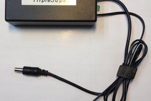
 Manu
Manu
 Thomas Van den Dries