Alastair Young
-
CNC Progress and Collet Chuck
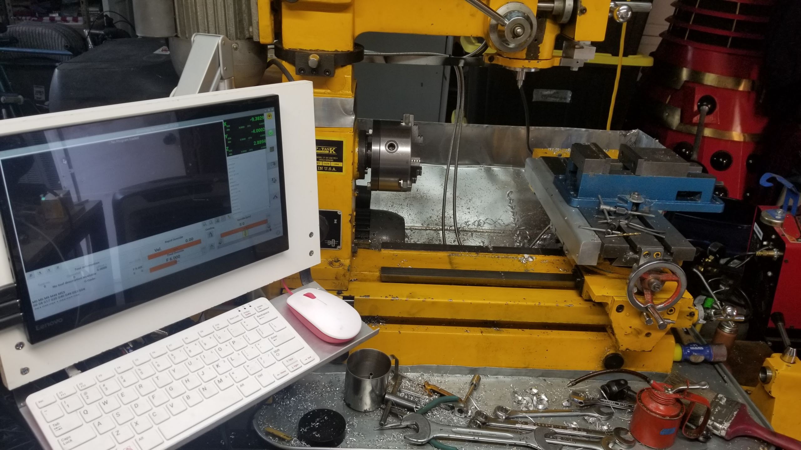
08/27/2021 at 04:18 • 0 commentsI now have a functioning CNC setup, and have started to learn how to use it in lathe mode. See the sub-project: linuxcnc
I also picked up an ER-40 collet chuck that fits directly to the lathe spindle nose - no adapter required. This is the only chuck I've ever seen listed that fits the Shoptask. I don't have any collets for it yet, but is seems to be perfectly concentric - at least I get the same runout of 0.0005" on the ER-40 taper as I do on the MT4. Spindle maintenance time...I found it here: HHIP 3901-5038 ER-40 Collet Chuck, 132 mm Diameter x 42 mm Height
![]()
![]()
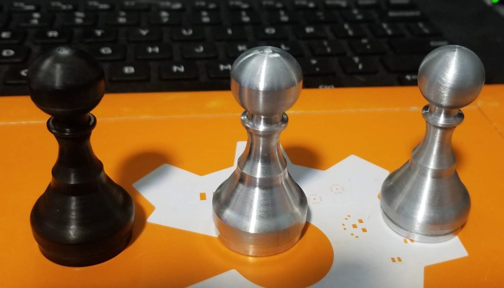
Sequential pawn efforts.
-
CNC controls and more tools
06/03/2021 at 01:21 • 0 commentsI've been putting some time and money into the CNC controls and I'll be adding that as a separate sub-project. Most of the components for the controller, drivers and motors are purchased and assembly is underway. I'll document it in a separate sub-project.
I picked up a Mitutoyo 155-903 Telescoping Gauge Set on eBay for $60 (list is ~$170). My cheap Chinese ones just don't work right - poor manufacturing. This set is used and was listed as having a broken unit (plunger missing on the smallest one) but the missing part was in the bottom of the wallet and just needed reassembled. It also came with an extra B size gauge. A bit of light oil and a couple of Kim Wipes and they work like new.
-
Y-Axis Bearing Upgrade
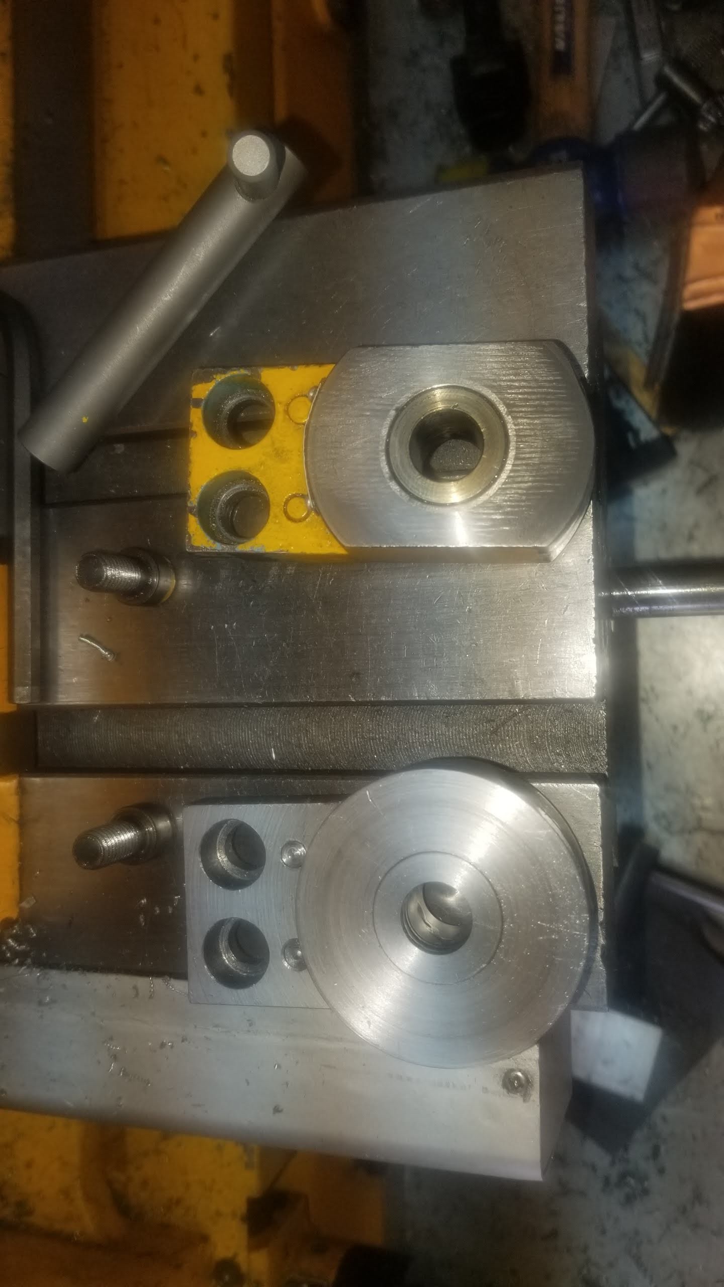
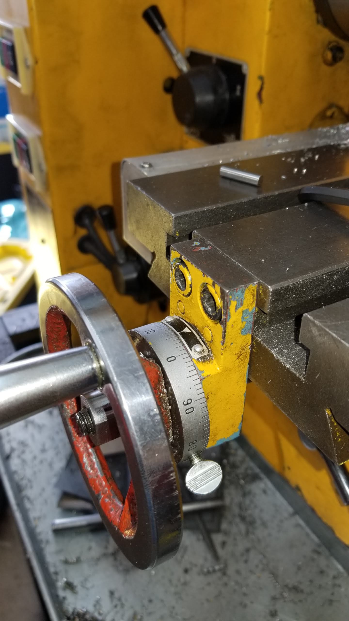
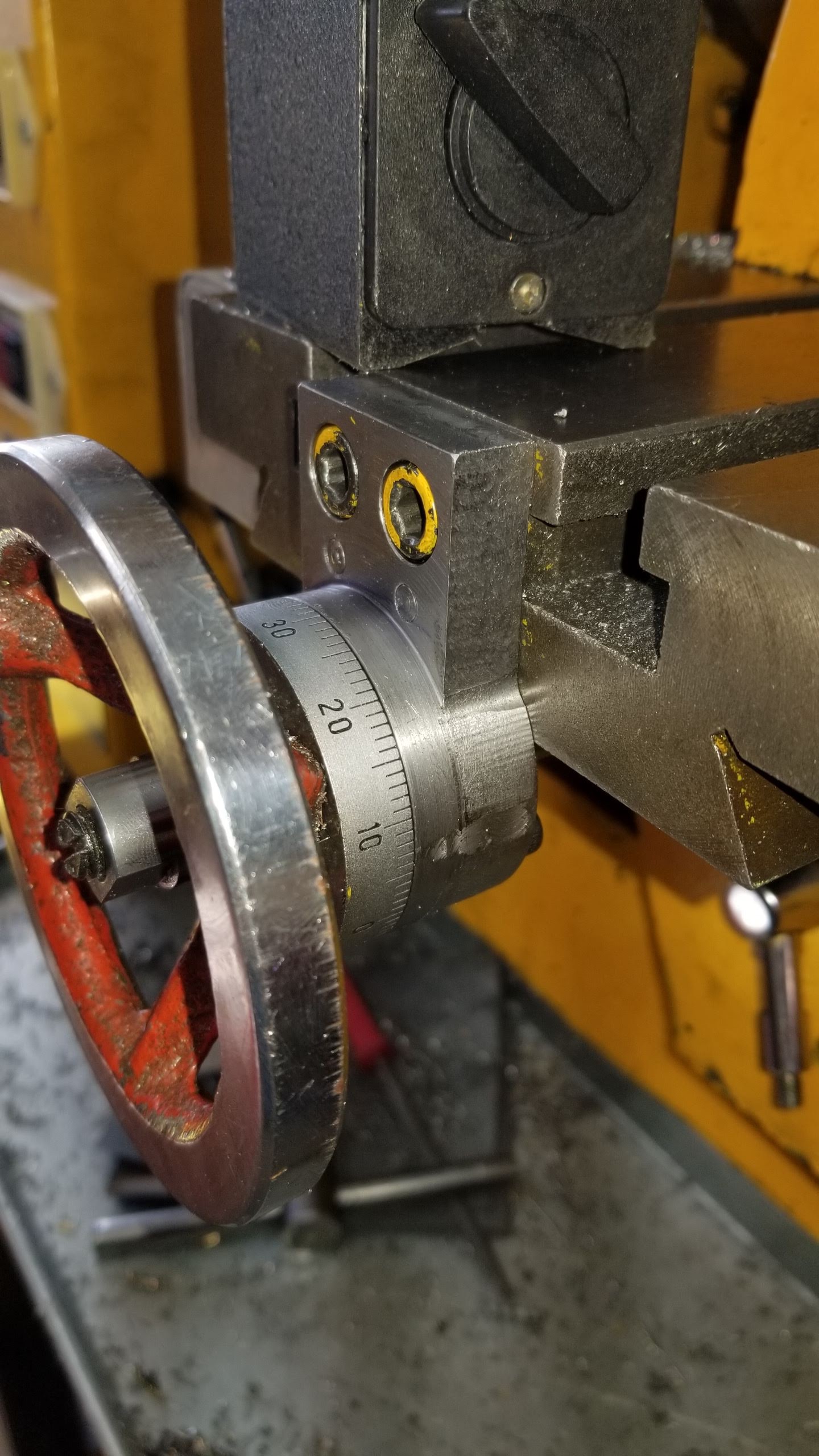
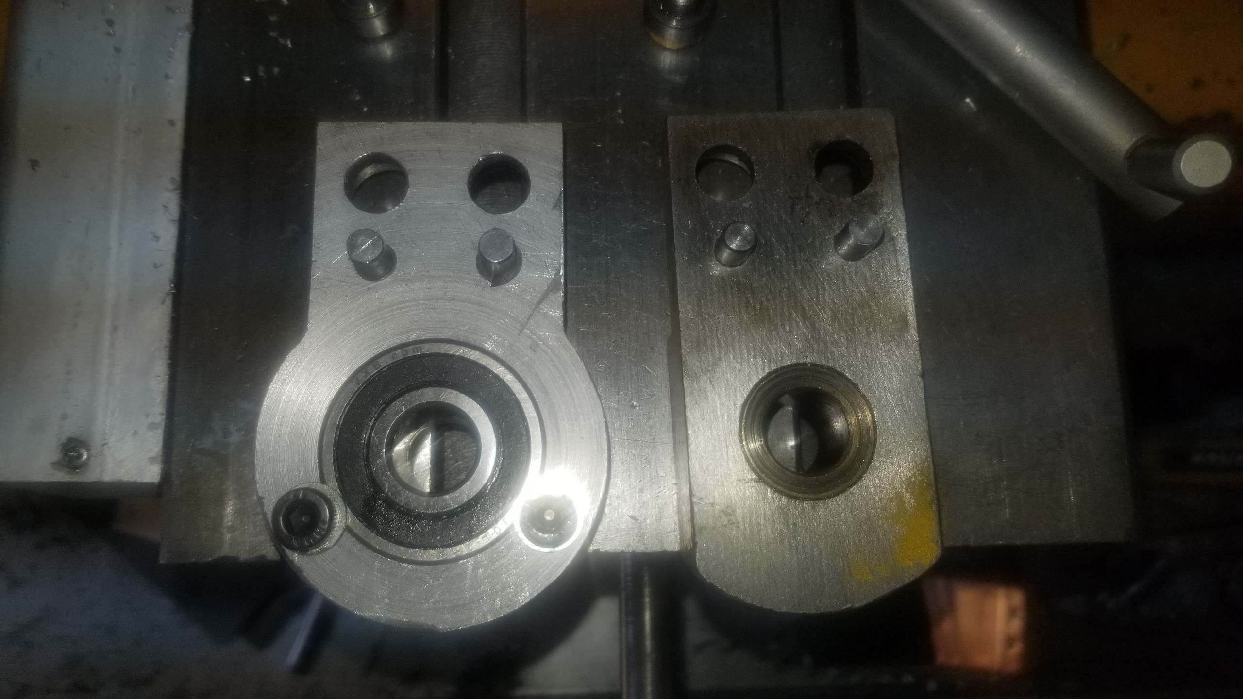
04/13/2021 at 15:40 • 0 commentsUpgraded from a plain bearing held in with a set screw to a double row angular contact bearing.
![]()
![]()
![]()
![]()
![]()
![]()
-
Lessons Learned and Tooling Updates
12/03/2020 at 05:03 • 0 commentsIn order to build the steam engine I acquired a bunch of tooling.
- a few small tap and die sets. For each size I purchased taper, plug and bottom taps, two drills and the matching die.
- a teeny drill chuck with a knurled handwheel for hand feeding little drills. This has a half inch shank. Random amazon seller.
![]()
- 3" x 3" x 3" angle plate from littlemachineshop.com I machined some 3/8" tapped holes in this on one side to clamp the steam engine to and also machined the sides of the ends so I could indicate against them. With the engine chassis clamped I could work on the chassis casting on its side, at 45 degrees (in the vice) or vertical (hanging off the side of the table.)
- HFS (R) Type B V-Block & C Clamp Set (1-5/8"×1-1/4"×1-1/4") off Amazon. At least that's what I ordered. The ones I received are much bigger - 70mm x 45mm x 40mm approx. I'm not complaining. This came in handy for finishing off the eccentric.
- Springy tap drivers, two sizes. Not great quality, but they work. Amazon again.
- A couple of 12mm square by 200mm tool steel blanks. Amazon.
- 1/4" right and left tools and a couple of square blanks the same size. These were for getting into the crankpin machining. I was able to space them up to get to spindle height. Littlemachineshop.
- Right and left 1/2" lathe tools. These turned out not to work as it seems the tool height on the standard toolpost is metric so these sit 0.7mm high. Littlemachineshop.
To build this project I had to machine at all heights in my Z-space, with a bunch of different tooling lengths. This has always been a bugbear on this machine as the MT3 extension is extends the spindle more than the spindle has travel, so there are places I just couldn't get to in the past. With the tooling I have now this is less of a problem, though it results in a mixed bag of solutions.
- The standard MT3 3/8" mill holder covers a fairly wide range, and can get close to the table with the MT3 extension. Some extra range can be had by not using the flat when tightening up, and I have one long (1/4") cutter now as well.
- The MT3 ER32 collet chuck is a bit longer than the mill holder and allows a lot of flexibility on tool extension. In particular long drills can be clamped on the flutes to make them as short as needed.
- The teeny drill chuck can be held in the regular drill chuck for extra reach on small drills.
- I have a 5/8" MT3 collet. I made 1/2" and 3/8" aluminum collets sleeves to fit in it, allowing me to hold tools or the teeny drill chuck close to the head or on the end of the MT3 extension.
While the randomness of this is a bit annoying it is no longer blocking. I don't have to dismount the work and space it up just because I'm changing from a mill cutter to drill like I used to some of the time.
One major annoyance was the lathe toolpost and tooling. I essentially have only one lathe tool that works - a 12mm 60 degree threading bit. It's the only one that gets to the correct spindle height on the standard turret toolpost. The Shoptask "quick change" toolpost is a bad design. While it is adjustable, it's hard to do, and quick change it is not. Worst: the tool holders are narrower than the tool post, so the toolpost gets in the way. Don't get me started on the "compound". Which is why I've ordered a Multifix 'A' toolpost from PeweTools in Deutschland. With a bit of luck it will be here by Weihnachten. That's the topic for the next sub-project.
While using the DRO on a real project for the first time with many hours of use I find that I almost never look at the handwheels anymore - or worry about backlash much. I'm habitually locking the unmoving axes. This is removing my concern about retaining inch leadscrews which opens up the option of cheap metric ballscrews when I get to the CNC stage. Prices for these are now under $100 per axis. While CNC with DRO position for feedback should care less about backlash than a "blind" setup, backlash should still be minimized. At his point it is up to 75 thou on the Y axis as apparently the set-screw on the acme nut has loosened again.
Another concern for the lathe is the distance from the center of the toolpost to the edge of the table. If the swing of the work (and chuck jaws) hits 200mm, something would always hit the table if I got in too close. Now that the DRO scale is on the chuck side, this issue issue is even worse. I ran into this cleaning up the steam engine flywheel (over 6") in the 6" 4-jaw chuck. I ended up using the 200mm tool blanks extended way out to get it done. Not very rigid. A partial solution would be a smaller 4-jaw chuck. Like a 5" or 130mm like the 3-jaw. Another solution would be to make a toolpost support block that extends forward - somewhat like a traditional compound extends the toolpost out on a normal lathe. When I do the ballscrew conversion I think I'll spin the table round so the gibs are towards the lathe chuck and the DRO is safely on the other side. In the meantime if I do need to do big things I can use a beefy boring bar tool on the Multifix to reach out over the divide.
-
Steam Engine
12/03/2020 at 04:33 • 0 commentsMost of the recent machine upgrade activity has been in the stand upgrade sub-project in which I modified the stand to include under-machine tool storage and added chip catching metalwork. The machine is now out from the wall and turned around and I made myself a nice big workbench. The usability of the machine and space is radically improved by all this so I was inspired to actually build something - a PM Research model steam engine kit. This was also inspired by two YouTubers who are building the same kit. Blondihacks (a hobbyist with limited space who somewhat learns as she goes) and Joe Pieczynski (a professional machinist with years of training and experience whose professional pride just can't bear the fact that new hobbyists are relying on other hobbyists on YouTube for how to do things). I recommend both the kit and both YouTube series. In practice there is stuff to be learned from both.
Photos of my steam engine build.

Drilling the mounting holes in the bearing caps -
Z axis complete
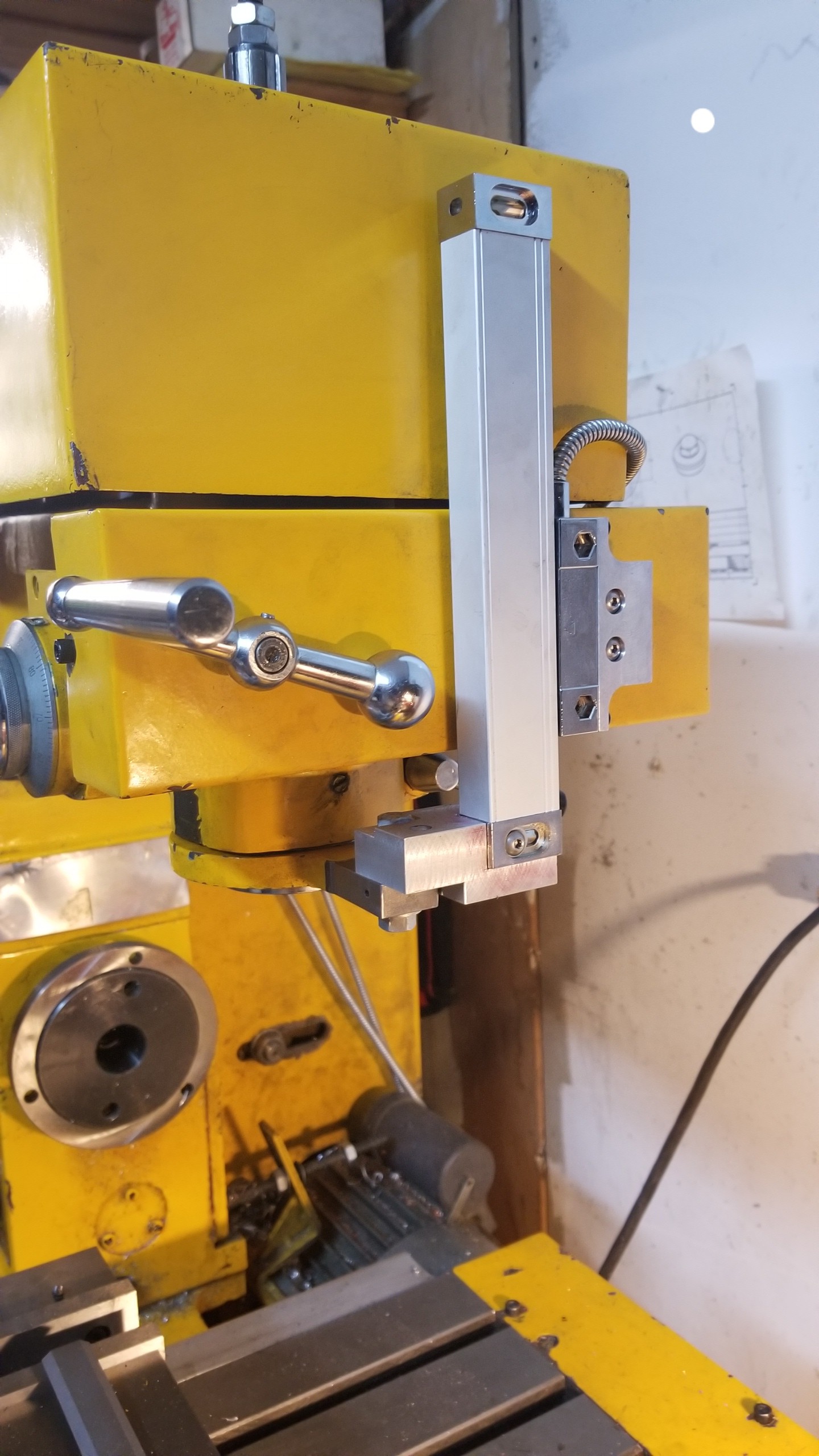
06/30/2020 at 20:31 • 0 commentsThis is all buttoned up with a hole in the belt cover for the bracket. I now have 6 knurled point set screws with Loctite holding the supporting ring in place. I also swapped out all the set screws in the z-axis drive with these. Repeatability is good except for when the quill itself rotates it varies about 0.005". The screw-pin that prevents the rotation has some play, so making a new one would help, and maybe a spring.
Edit: new screw turned down from a cap-head with a nice snug top and half a turn of tension on the spring and it's 0 to 1.5 thou variance from quill rotation along the travel, and the backlash is gone.
Also the quill return spring is needs more tension - the drive needs to push it up at the top of travel.
The scale mounting is more rigid than it looks - there is a second screw holding it to the bracket at right angles to the visible one. The head on it is low enough to let the visible screw pass over it.
![]()
-
Z axis again
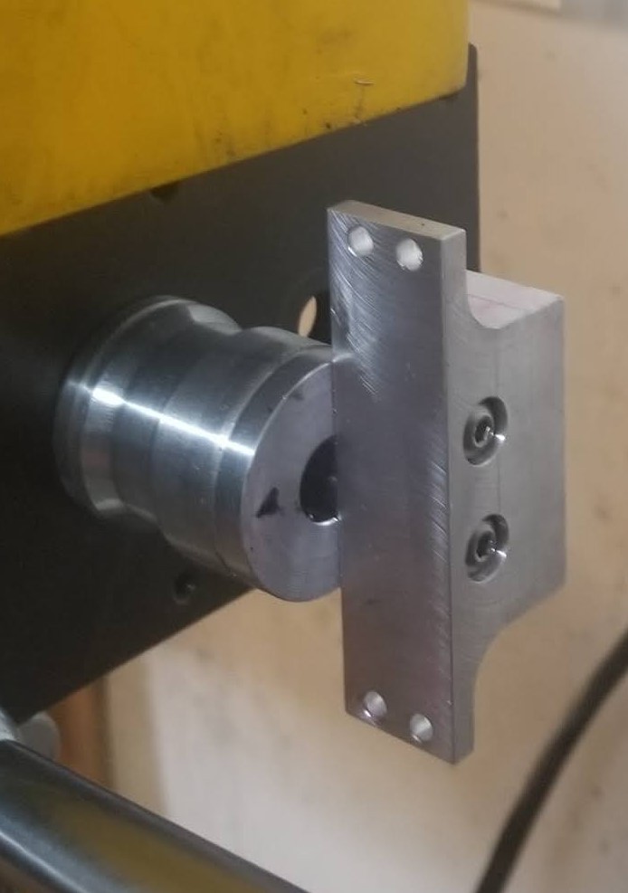
06/26/2020 at 04:57 • 0 commentsThis is the two-part bracket I came up with for the z-head. The round part will need a hole drilled in the belt cover. There is clearance above and below for the belt.
![]()
Once fitted I find that the scale is now loose. It is not loose in my bracketry, it is the oil-seal ring that it attaches to is only held on with two set screws. These were mounted front and back to minimize wobble for the front mounted depth stop, so I had made new dimples for them and rotated the ring 90 degrees. A little bit of milling and they are all loose. So I am ordering new knurl-grip set screws from McMaster - this time they will be hex head not slot head and I'll install at least 4 of them. De-grease everything and use red Loctite. Maybe some Loctite on the ring itself too or some painters tape under it to make it a tighter fit....
These set screws come in a pack of 50, and I'm pretty sure there are several other screws on the machine that could use upgrades - like the ones that hold the acme nuts in place.
-
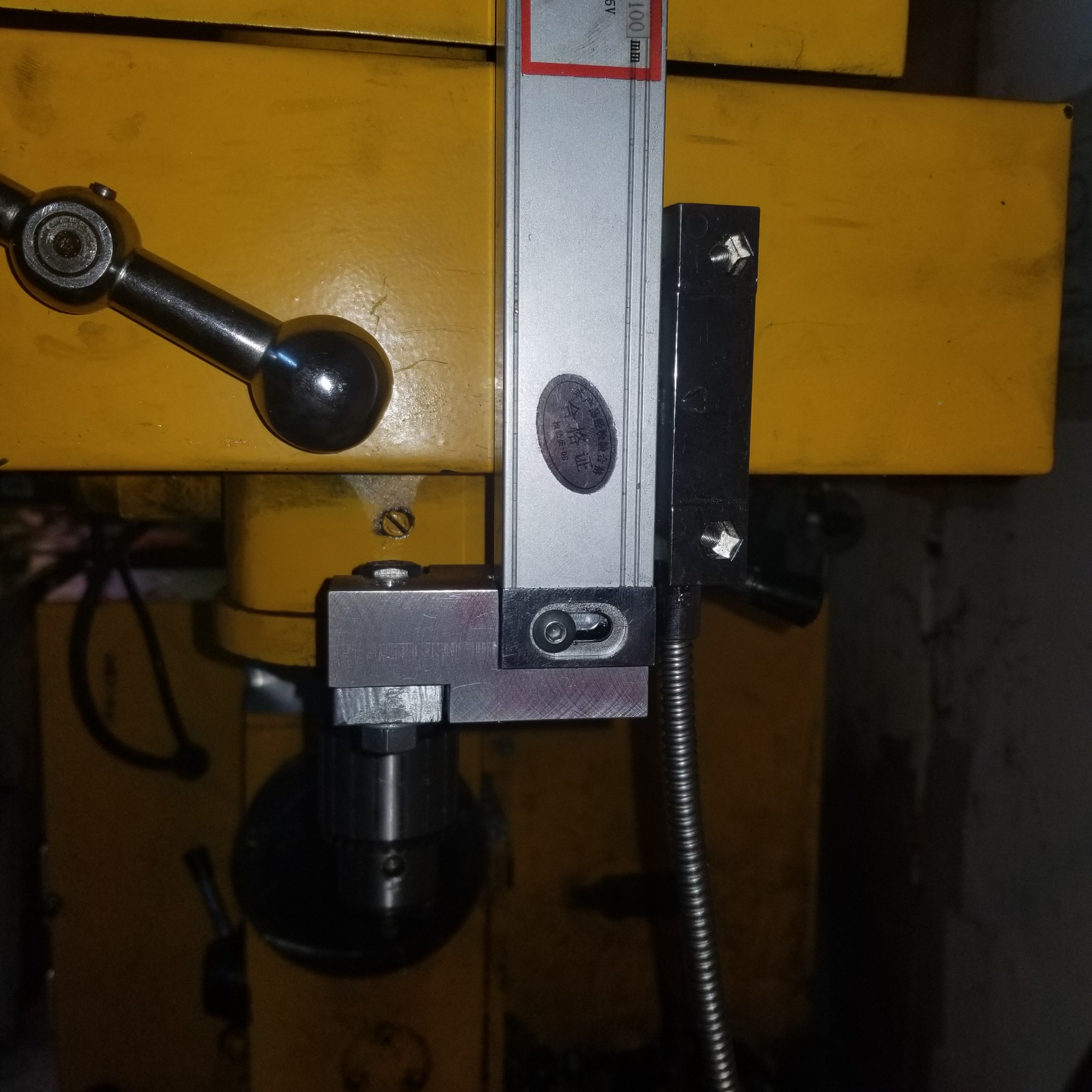
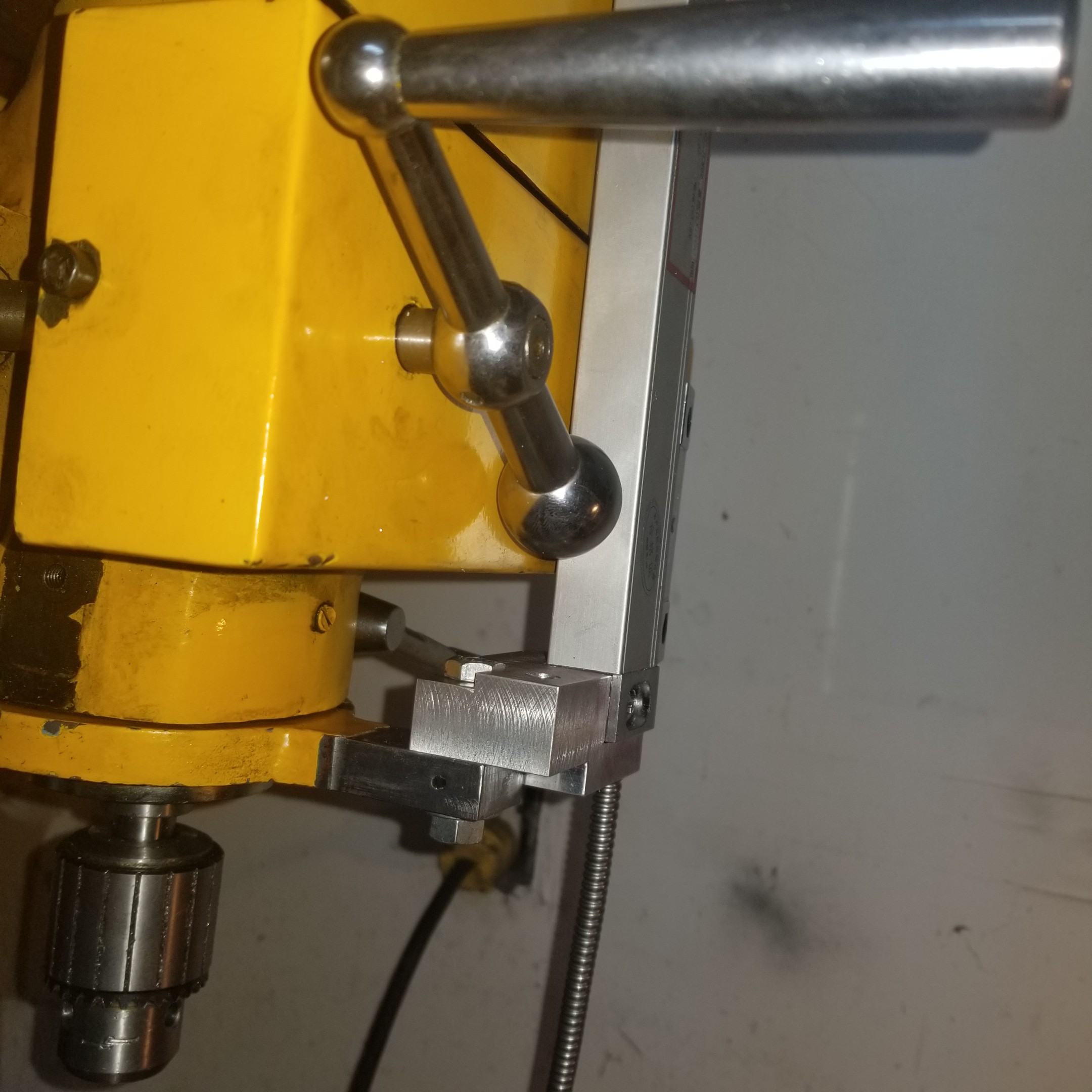
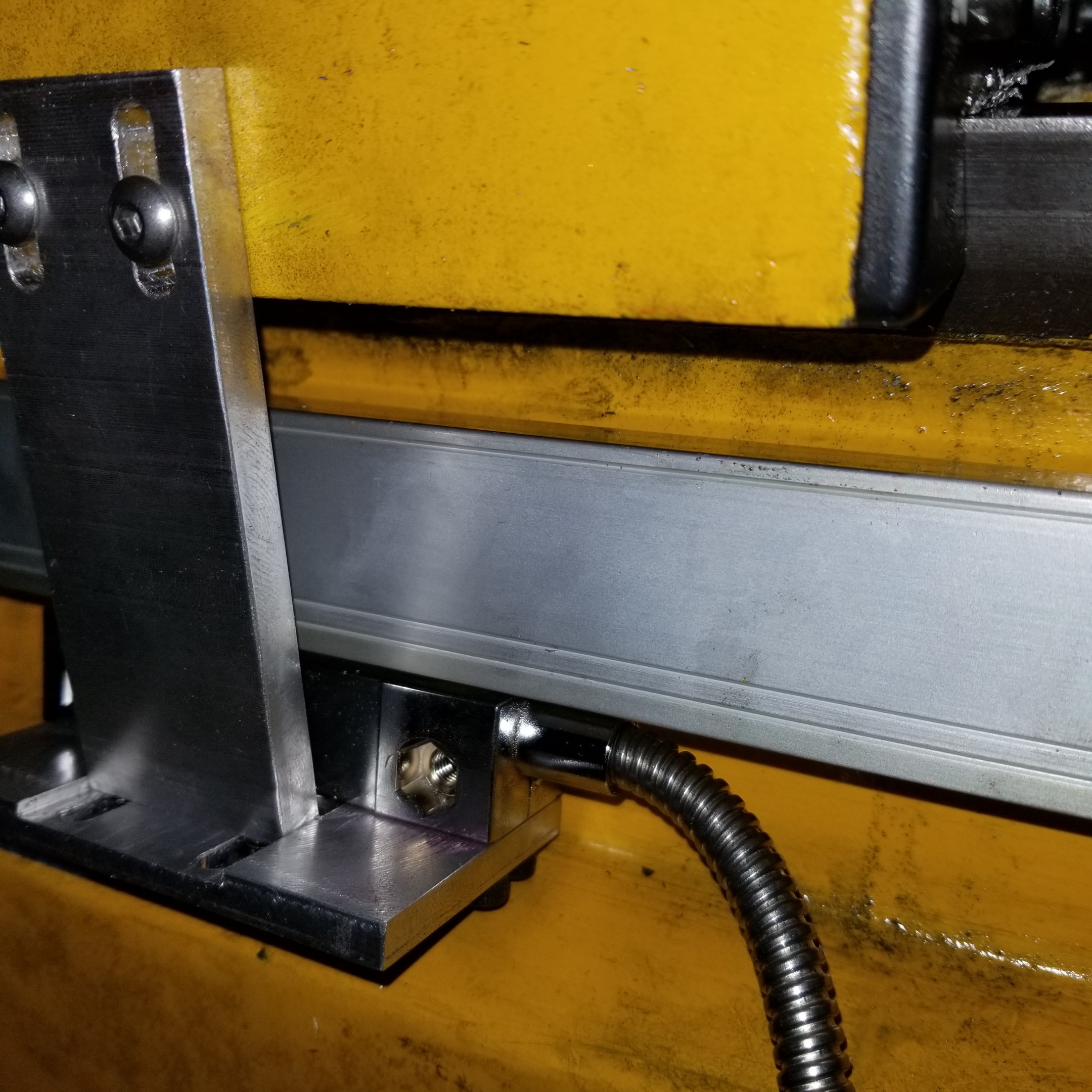
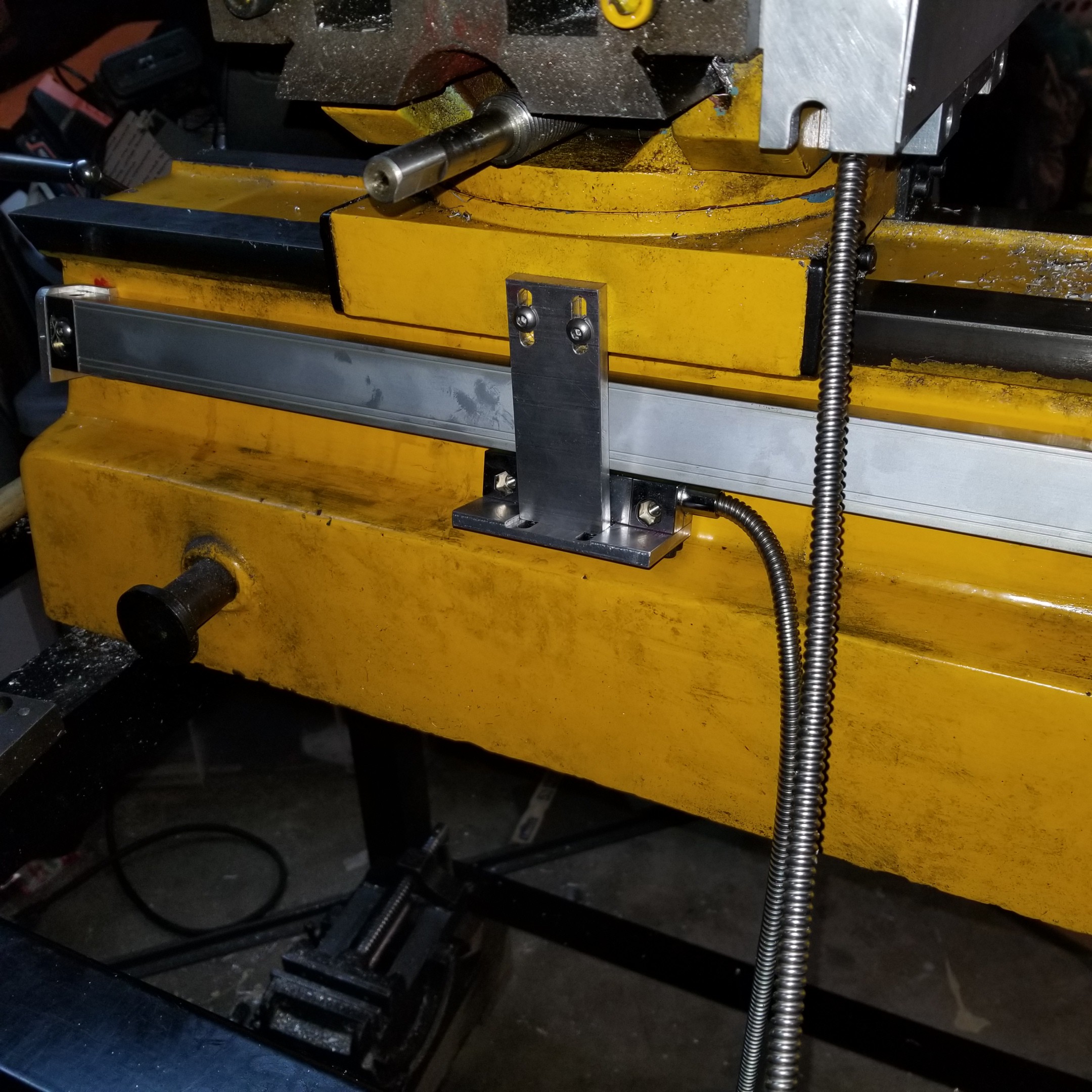
Z-axis dro scale mounted
05/11/2020 at 03:06 • 0 commentsI decided to mount the scale to the quill, repurposing the depth stop, It seems to be quite solid. The bracket for the head will be a challenge as the cnc belt and cover are in the way.
![]()
![]()
-
X dro head mounted
05/06/2020 at 05:30 • 0 commentstight fit with regular cap screws underneath. I don't have any 4mm button-heads.
![]()
![]()
-
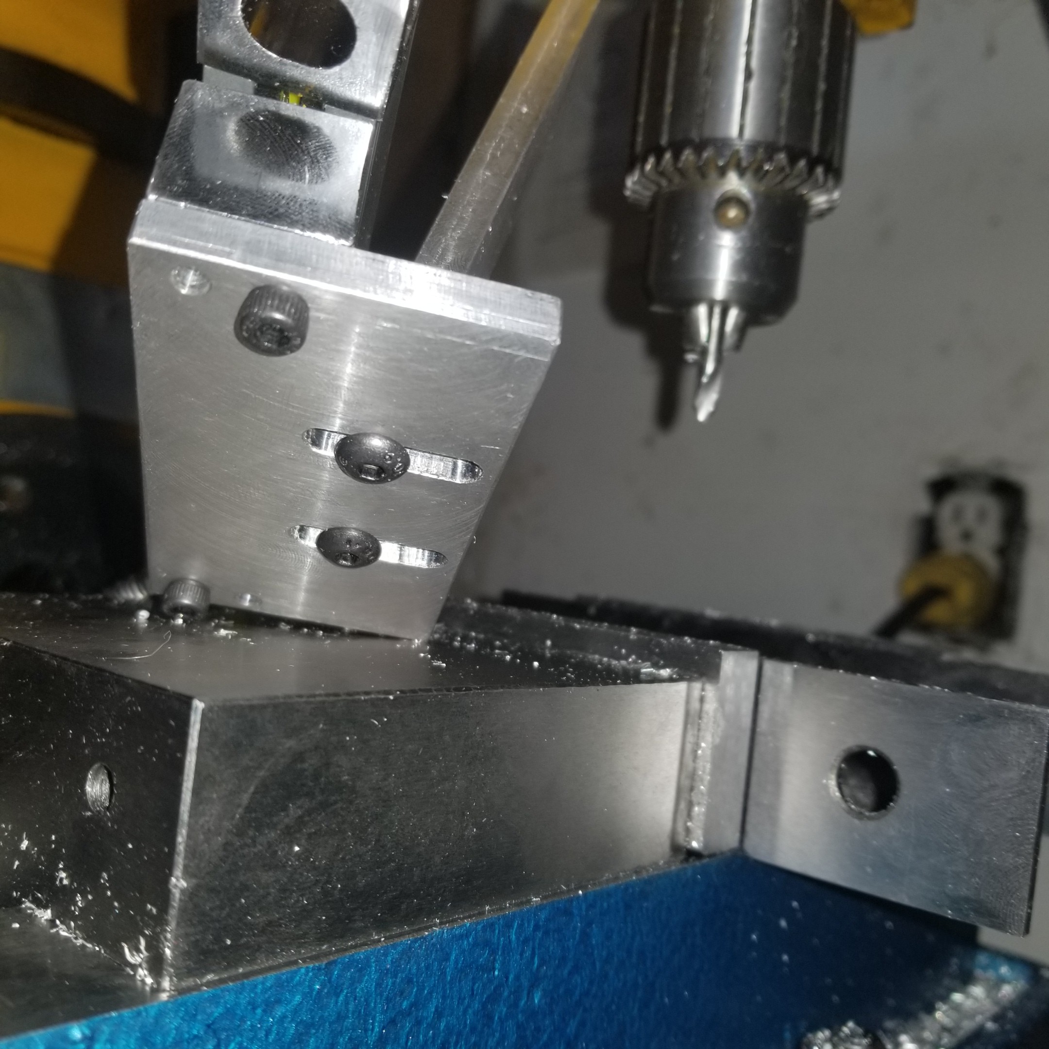
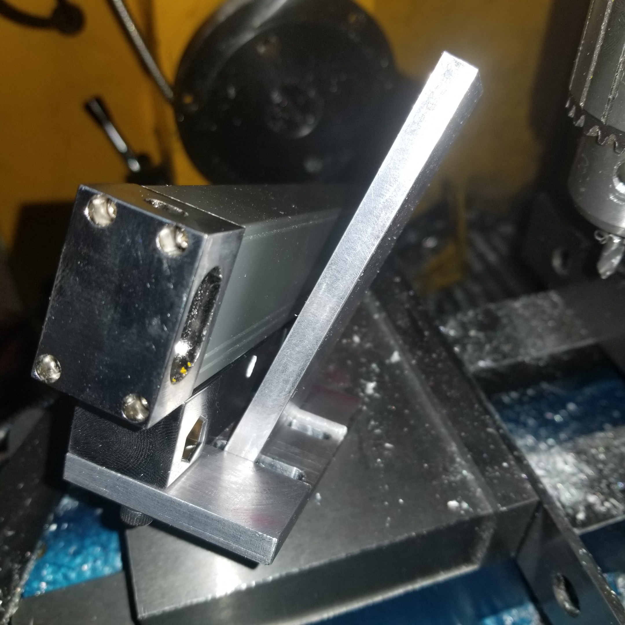
X axis dro head bracket
04/27/2020 at 04:24 • 0 commentsas the scale is flush to the casting and that is canted inwards, I need an adjustable angled bracket. Still to do: slots for the screws to mount it to the carriage. This way it will have adjustment in two axes. The angle was transferred directly from the angle between the bed and the outer face of the scale.
![]()
![]()
The Y axis DRO proved useful spacing the holes and slots fron center.
Reviving a Shoptask 1720 XMTC Gold 3-in-1
This thought project is notes on reviving my 1998 Shoptask 1720 XMTC Gold late-mill-drill