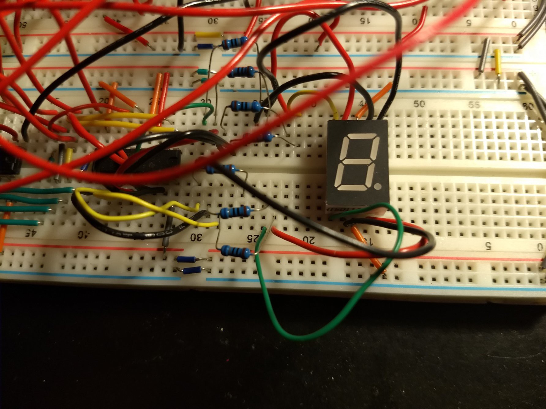
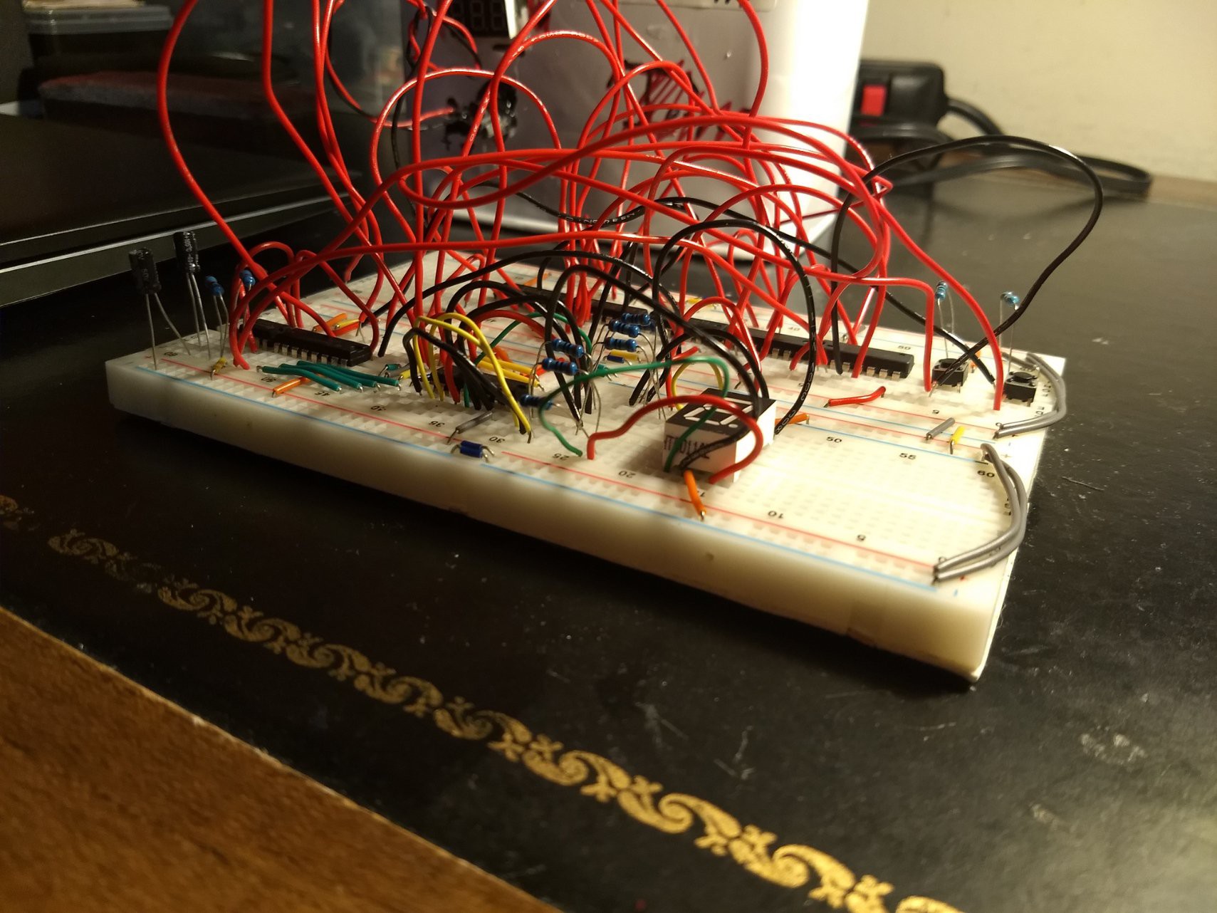
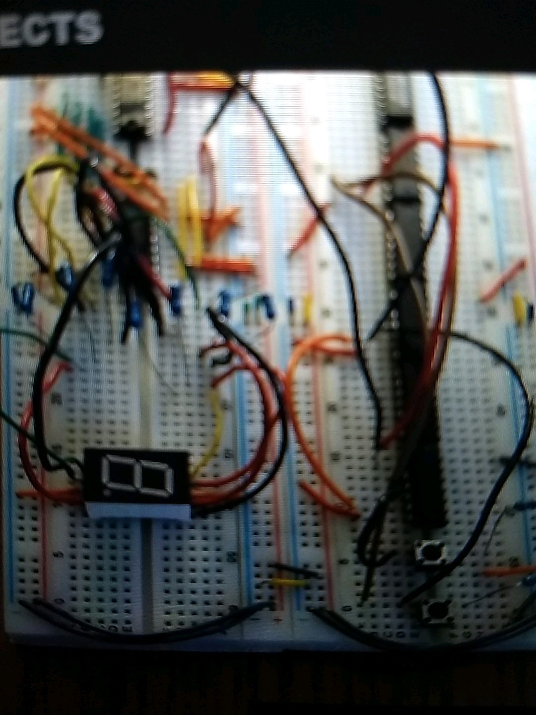
A one digit Scoreboard that keeps track of your score
To make the experience fit your profile, pick a username and tell us what interests you.
We found and based on your interests.
Gerber_Scoreboard.zipPCB Filex-zip-compressed - 84.79 kB - 03/27/2021 at 17:21 |
|
|
Schematic_Scoreboard_2021-03-27.pdfUpdated schematic 3/27/2021Adobe Portable Document Format - 93.16 kB - 03/27/2021 at 17:21 |
|
|
Schematic_Scoreboard_Sheet_1_20200211152921.pngUpdated schematicPortable Network Graphics (PNG) - 135.19 kB - 02/11/2020 at 20:33 |
|
|
Scoreboard_Schematic.pdfFirst Schematic from 3 yrs agoAdobe Portable Document Format - 47.50 kB - 01/25/2020 at 18:33 |
|
|
Hey Guys,
I have finally updated the scoreboard schematic to make it accurate and correct. Here it is:
The PCB part of the scoreboard is still in progress. A few weeks ago I got the PCB board and soldered all of my components on to the PCB board. Unfortunately it did not work and realized I made a mistake on the schematic. So I fixed it and could not buy it because of the Corona Virus in China (I used JLCPCB to buy PCB board). I am fairly new to PCB board and still learning it to this day. I also am trying to fix the PCB board to see if the functionality worked. I suspect that I arranged the switches wrong. However, where I live, it is cold outside so I cannot open the windows, which leads me into a stand still.
I want to give you guys an update and sorry for putting you guys in the dark.
I will give you updates as soon as the corona virus is done and I managed to fix my mistake.
I drew up a schematic for the scoreboard. Here it is. I have come a long way in drawing schematics.
I have stayed up until 1:30am which is last morning to figure out how to get the scoreboard to transition from 9 to 0 and vise versa. at first I used a bunch of logic gates and a flip flop at first but it is all in vain. Then I realized that I was overthinking this process. I need only 4 logic gates and three output with the first output at the and gate and the fifth output at the load pin of the sn74ls169bn. I did trial and error and intuition to get the logic output right. I test it out and it worked. This is the last part of which I want to implement into the circuit. All I need to do is to draw the schematic and the PCB board.
Here is the video of the circuit:
Here are images of the circuit:
Scoreboard
Create an account to leave a comment. Already have an account? Log In.
@Ken Yap Sorry I did not notice your reply. Thank you so much!
Become a member to follow this project and never miss any updates
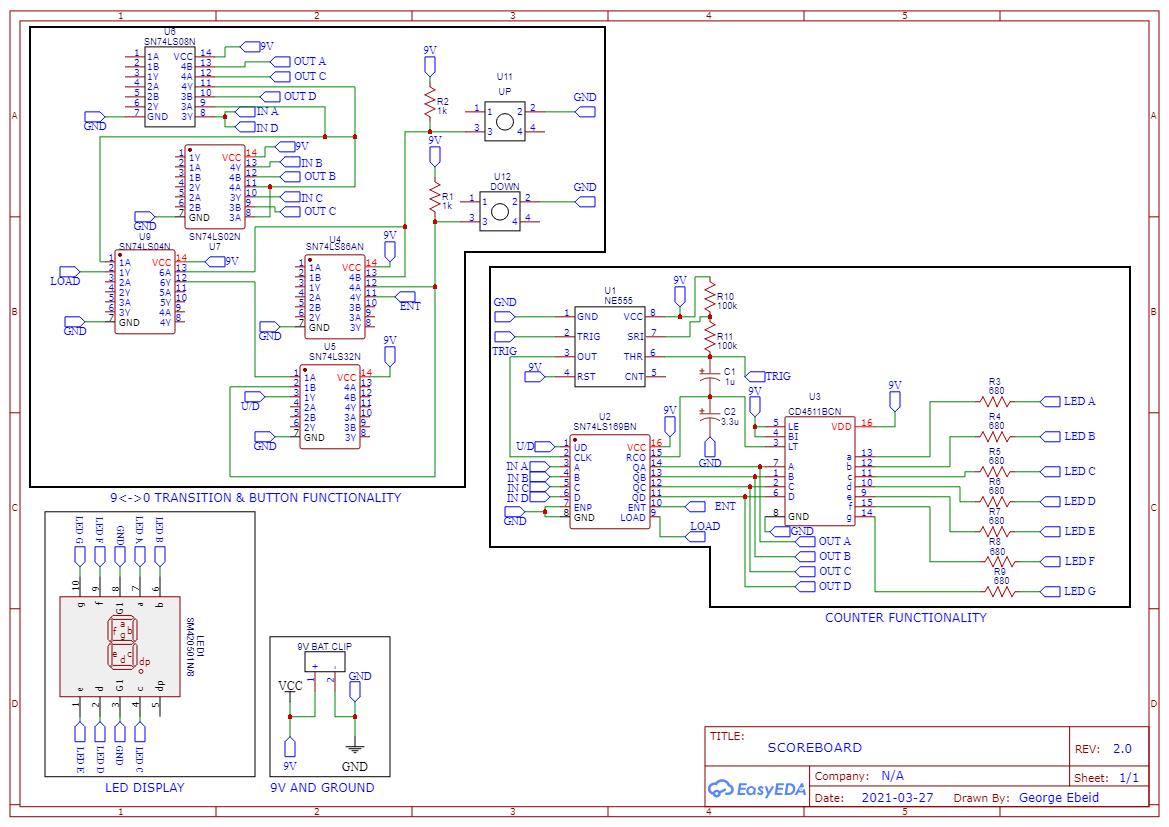
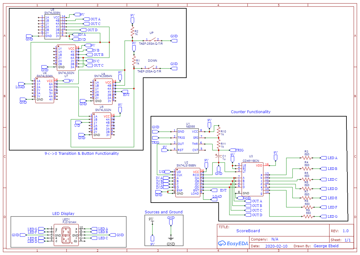
Good to see that you're into the good habit of drawing a schematic of the circuit first, and with an up-to-date Kicad version too.