 George Gardner
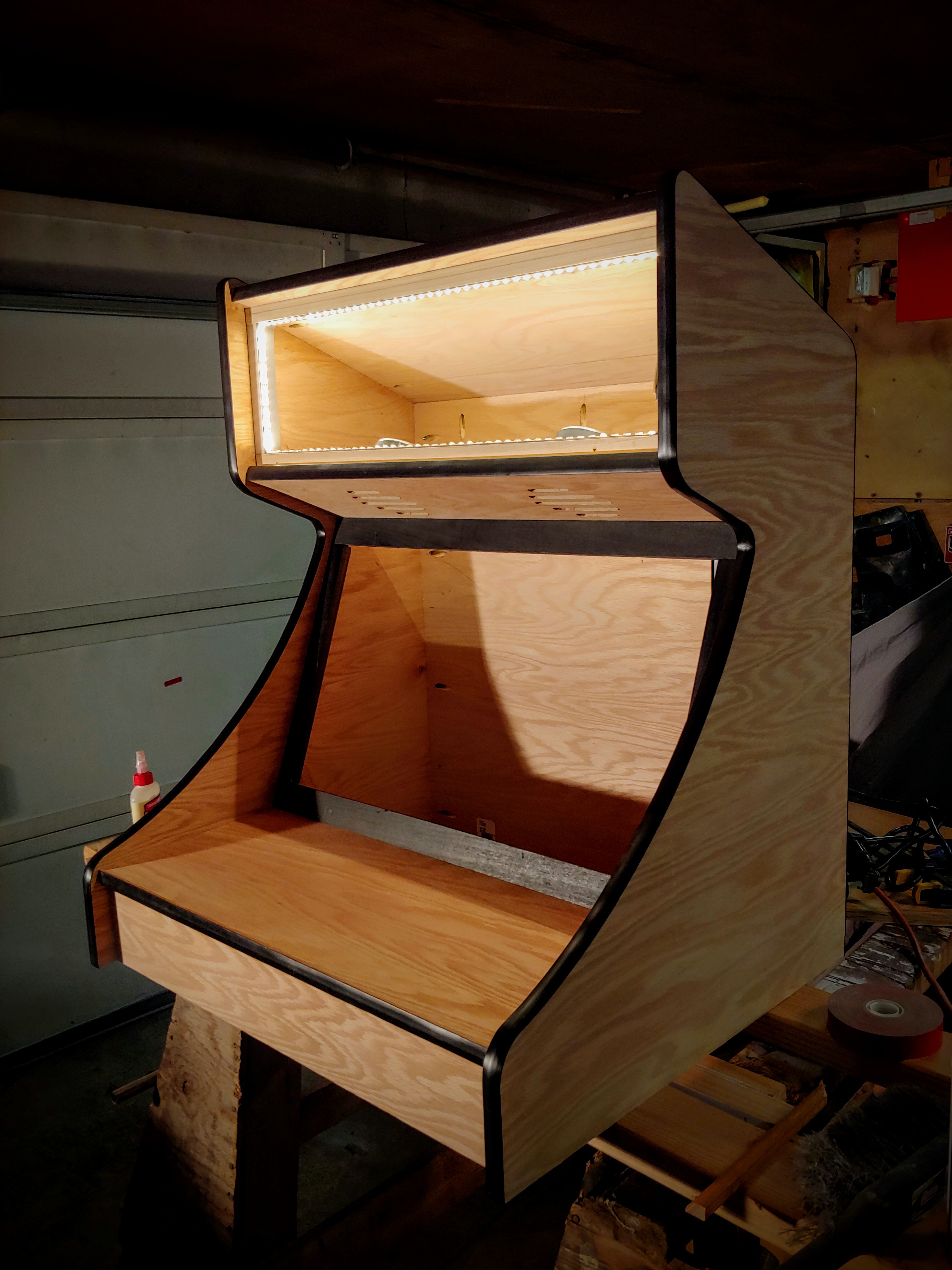
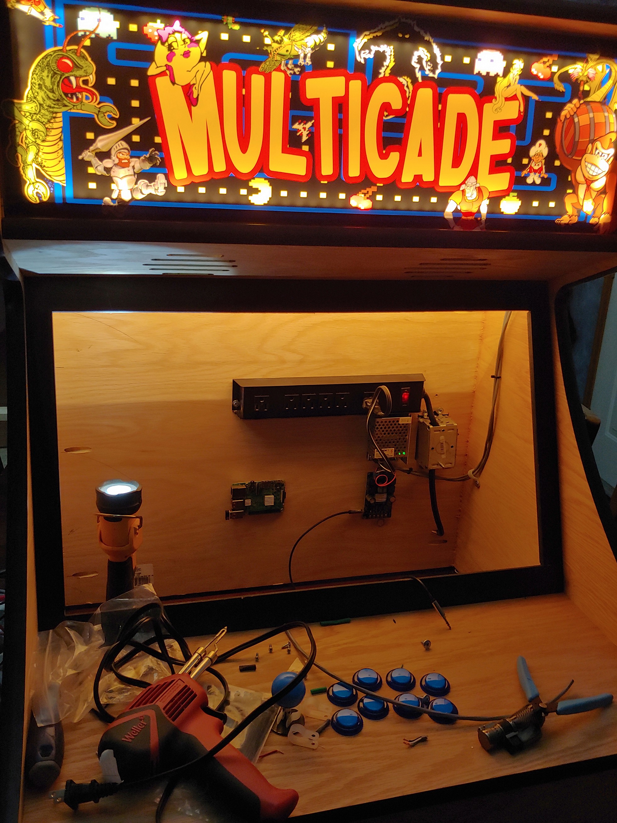
After completing the frame, I started with the LED light strip, which is located on the inside of the marquee receiver pieces. This is a short bit of a roll that I had left over from another project. It's a standard white LED strip (no color) and runs off of 24 volts.
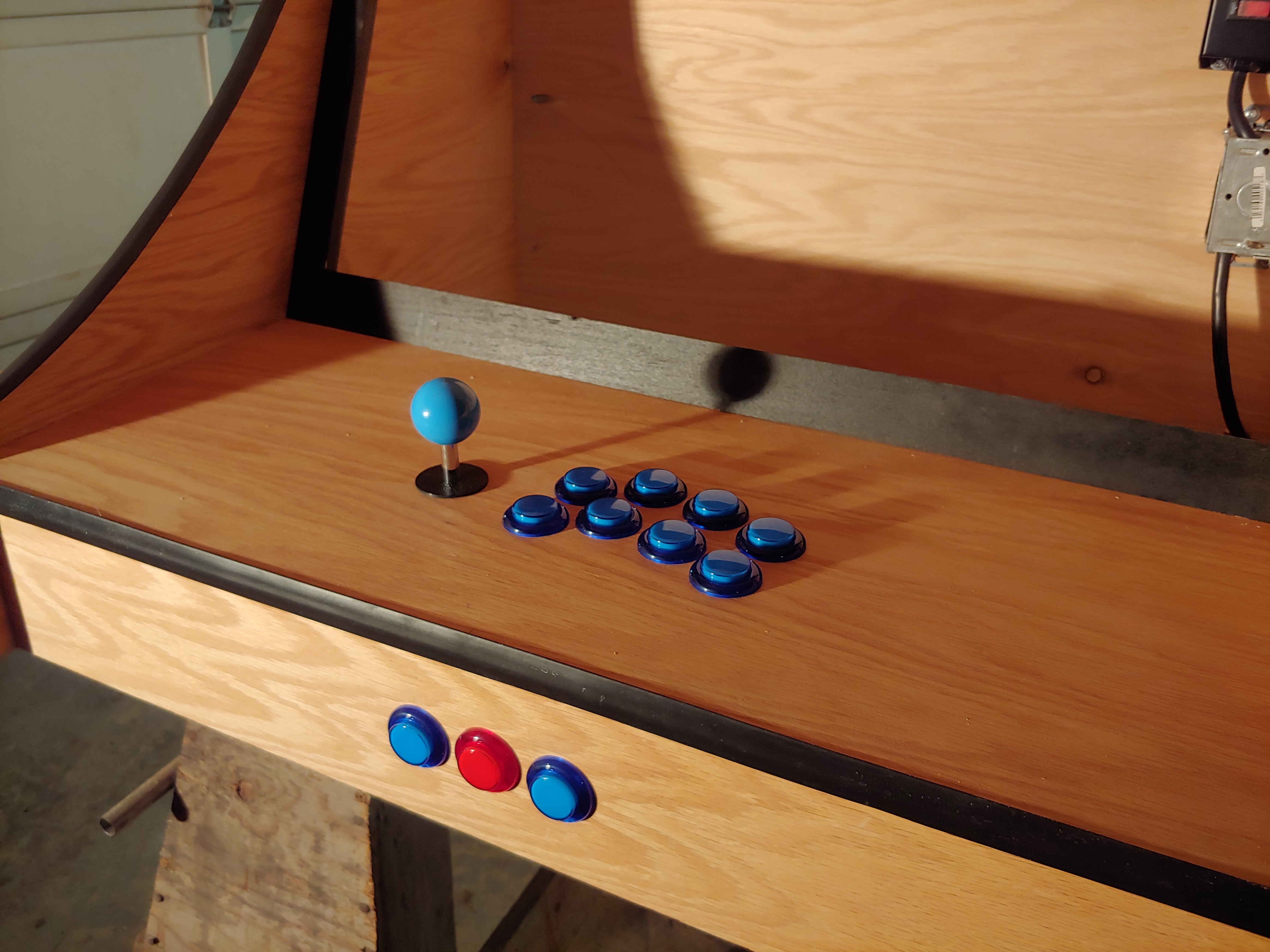
I then removed the joystick/button face and drilled all the holes for the buttons and joystick. I used a template from https://slagcoin.com/joystick/layout.html, and simply printed it out to scale, marking the center of all button & joystick locations. I opted to put (3) buttons on the face, which serve as the Select, Command, and Start buttons, respectively.
I wasn't happy with the length of the joystick against the 3/4" plywood, so I used my router to create a depression in the backside as shown in the image below.
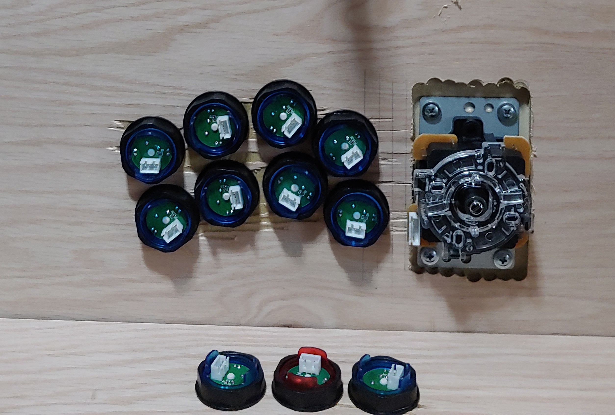
I don't believe it matters the orientation of the joystick, at least the one I used, as all the directions can be mapped within Retropie.
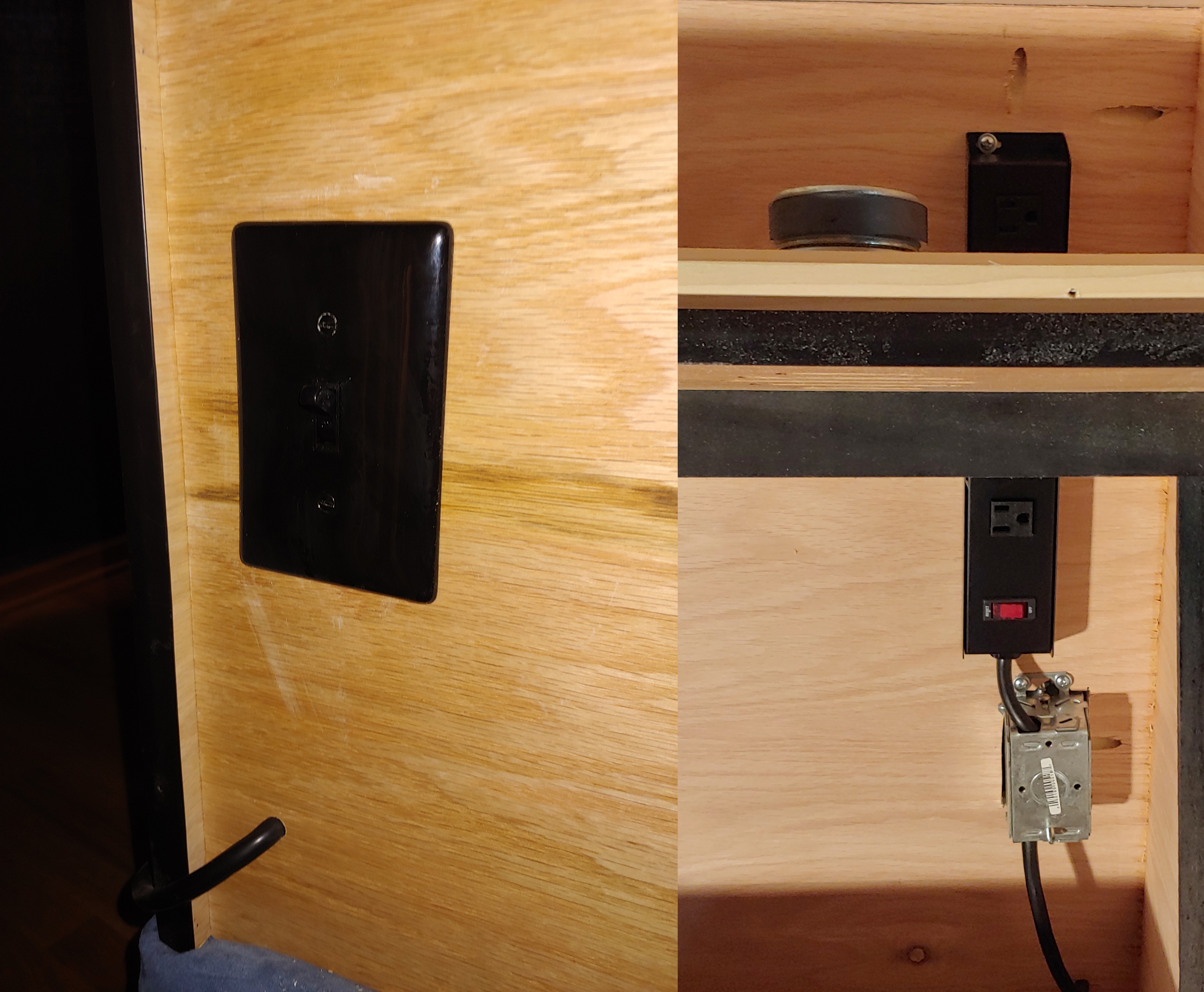
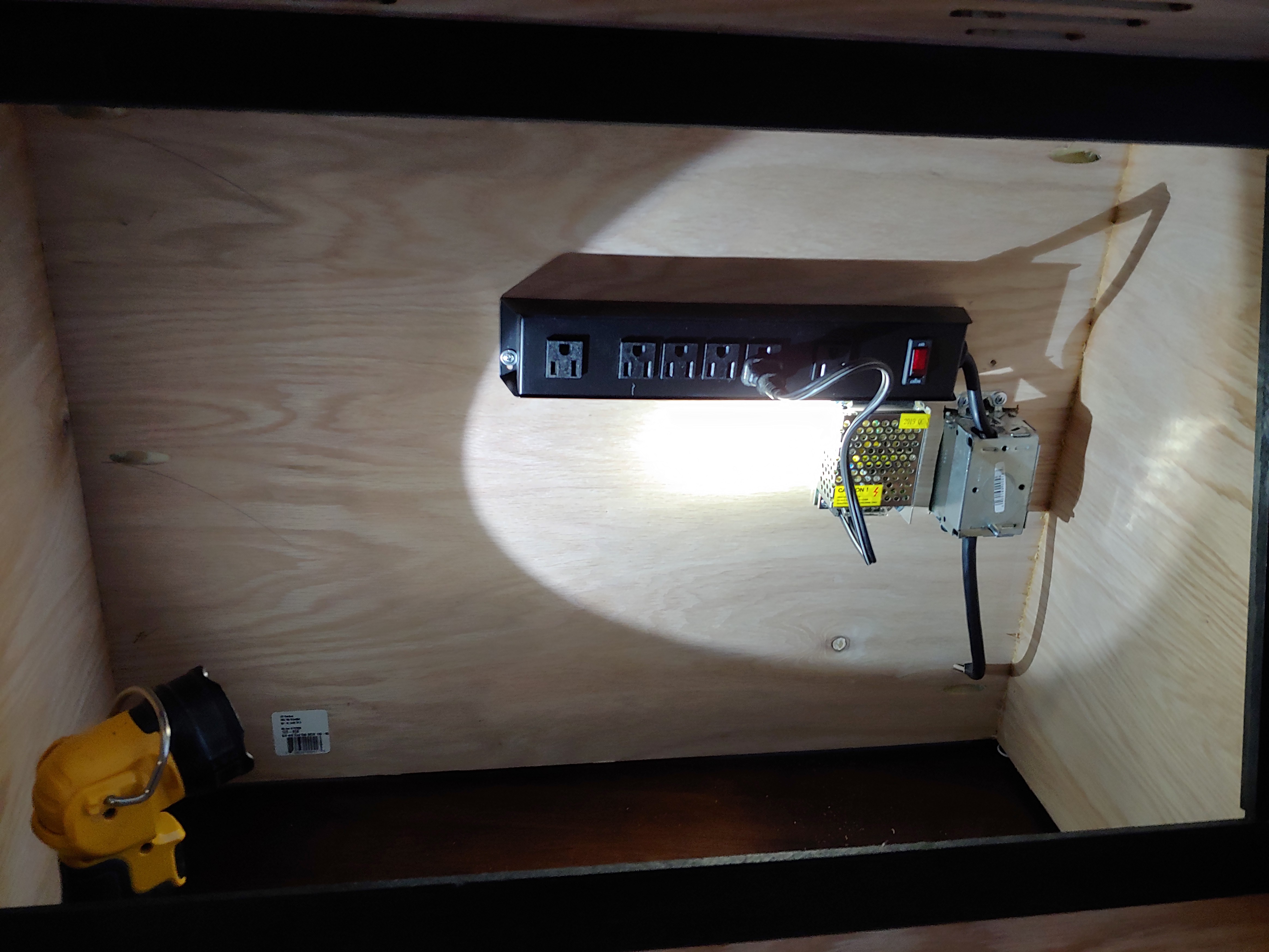
For the power on the arcade machine, I used a newly purchased power pack/splitter. I cut out an opening in the back of the machine and installed a gem box and a switch, cutting open the extension cord on the power splitter and wiring it into the switch.
For the LED power, I ordered a 24V, 1 Amp power supply on Amazon for $10.
I waited on the monitor install for ease of accessibility, as I could do all this work by reaching through the face of the machine. I installed a cheap class d amplifier that I had in the parts drawer, purchased on eBay a while back. It has a 1/8" stereo input, perfect for the raspberry pi.
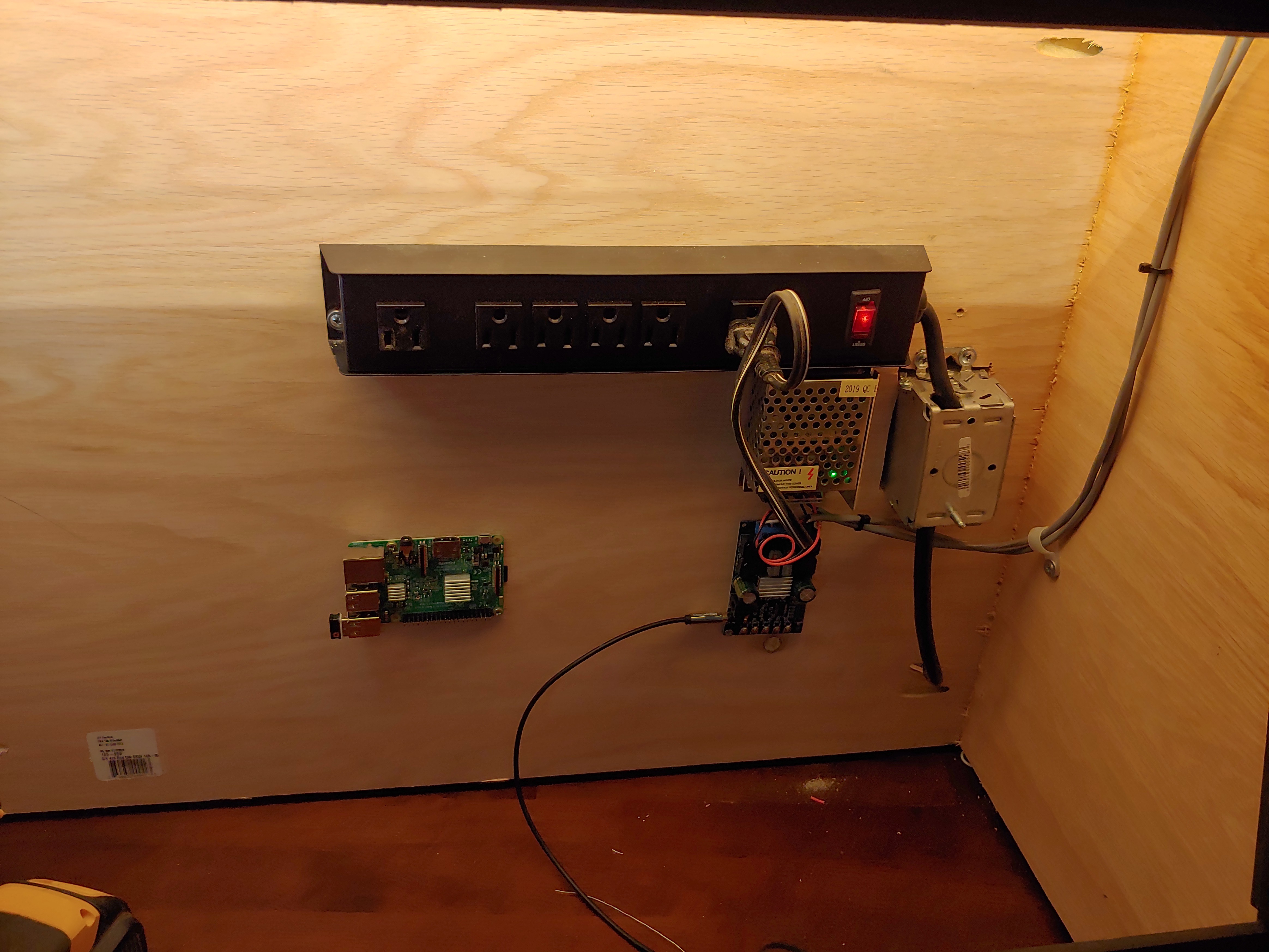
The LEDs pulled about 300mA, and on the test bench, I didn't see the amplifier go over 200mA, so a 1 amp power supply was perfect. The amplifier had a wide Vin range of 5v to 27v, so it worked with the same supply. After hooking the speakers up, I installed the marquee.
Discussions
Become a Hackaday.io Member
Create an account to leave a comment. Already have an account? Log In.