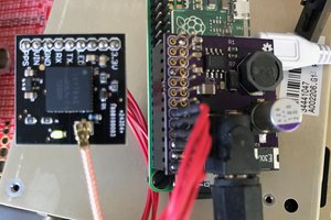
This clock borrows quite heavily from my GPS Clock project - specifically the v3 hardware. Instead of the Maxim display mux chip, 5 pins of the ATTiny841 simply drive N channel MOSFETs that in turn drive solenoids to strike physical chimes.
Like the talking clock project, because this is an aural clock, the standards for accuracy are quite relaxed. Really all you get from this being GPS driven is not ever having to set the time.
A lot of the firmware from both projects is carried over to this one - the time zone manipulation, DST code and GPS chip management code, specifically. All of that code is very mature and functions the same way here. All we really have to do is strike the hour chime solenoid immediately after the PPS pulse on the correct second.
Unlike the talking clock, the rules for the quarters are more strictly copied from the real Tower Clock. The quarters are timed so that they end before the end of the 59th minute and the first hour chime is actually synchronized to the top of the hour.
The firmware has code for all 4 of the quarter hours, but all but the top-of-hour behavior are disabled by default (I found it to be just too annoying every 15 minutes). The clock also has support for quiet hours, when the clock will remain silent to avoid disturbing sleep. The timezone parameters and quiet hours can be adjusted via EEPROM, but the clock as designed has no user interface at all.
The primary power supply is 15 volts with enough current capacity to drive one solenoid at a time (15 watts is plenty). 15 volts is a bit higher than the 12 volts the solenoids are rated for, but this makes the solenoids operate faster, which makes the chiming sound better. The logic system runs at 3.3 volts because the GPS chip requires it and there's no reason not to run the 841 at that voltage. 3.3 volts is supplied by a beefy LDO. The LDO has to handle a rather large power dissipation due to the relatively high voltage drop. Whether to use an LDO or a buck converter is kind of a borderline call in this situation, but I went for an LDO just for reduced noise on the 3.3 volt rail. There's also a bulk cap on the input power just to take some of the edge of the surge current the solenoids are apt to demand, and to absorb any coil collapse power that makes its way back through the flyback diodes.
Pulsing the solenoids for about 20 ms with 15 volt power makes for a pretty good strike. The solenoids and chimes are mounted on a 3D printed frame. There's also a 3D printed head for the solenoids, since using plastic instead of metal makes for a more pleasant sound from the chimes.
Alternatively, instead of using GPS and a microcontroller for the chimes, one can use a Raspberry Pi Zero W. In this configuration, you just use 5 of the GPIO lines to control the solenoid MOSFETs. The Pi runs NTP over WiFi to get good time and runs a python script from cron to do the chiming. This time the daughterboard has an AP63205UW buck converter to generate 5 volts from the incoming 15 volts. The buck converter is used because the Pi Zero draws enough current to make the power dissipation of an LDO much more of a concern. For convenience there's also a console terminal interface on the board to provide console access over serial if necessary (though recent versions of Raspbian have the ability to bootstrap WiFi configuration and SSH access through the FAT boot partition, so there's much less necessity for this anymore).
 Nick Sayer


 alnwlsn
 Sebastian