 Paul Gould
Boards can in from JLC PCB, components can in from LCSC and Mouser.
Hand populated the first one, testing as I went. I have a stencil for the next few.
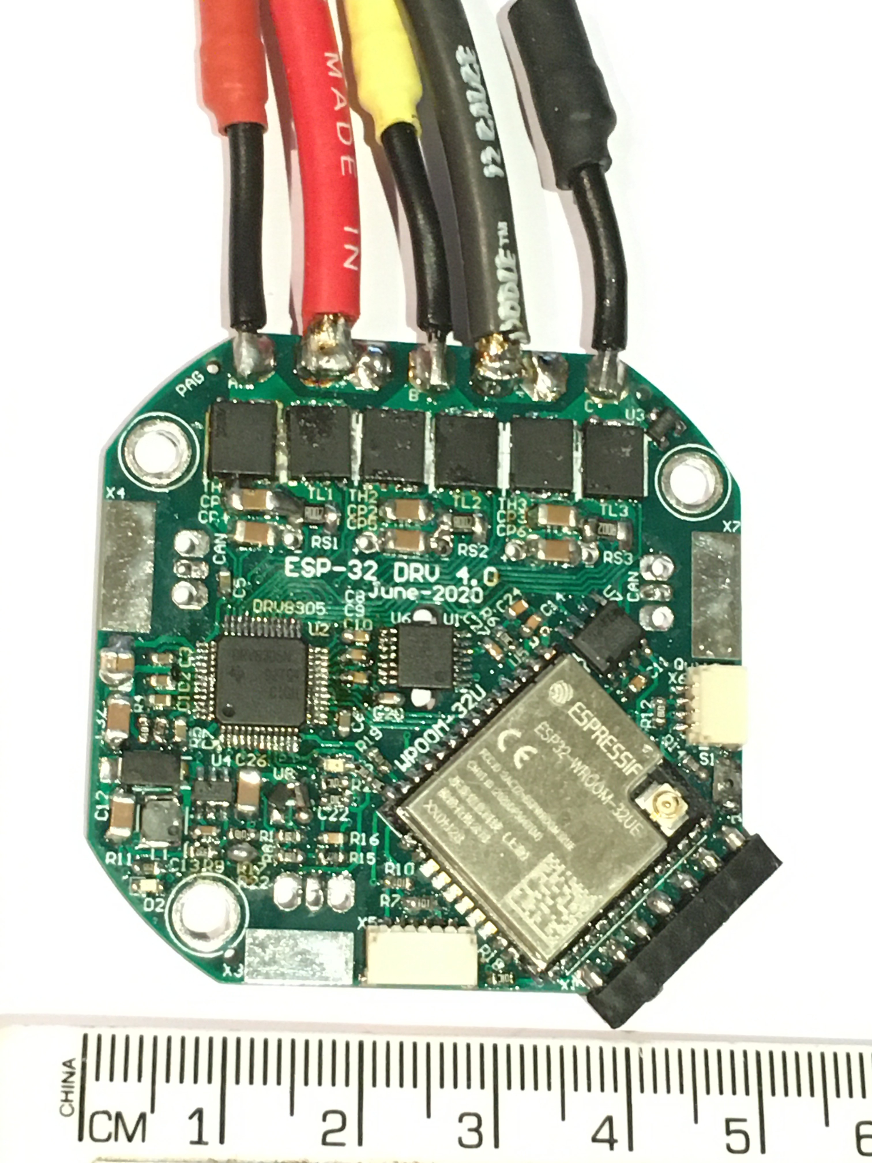
A few little mistakes.
- Auto Power switch over between USB 5V and Battery Voltage had a high forward voltage and had to be replaced.
- Needed a pull down on ESP-32 IO12
- Had to Parallel Caps for the Charge Pump because I ordered the wrong one.
Programs via Arduino IDE using USB-TTL-3V3
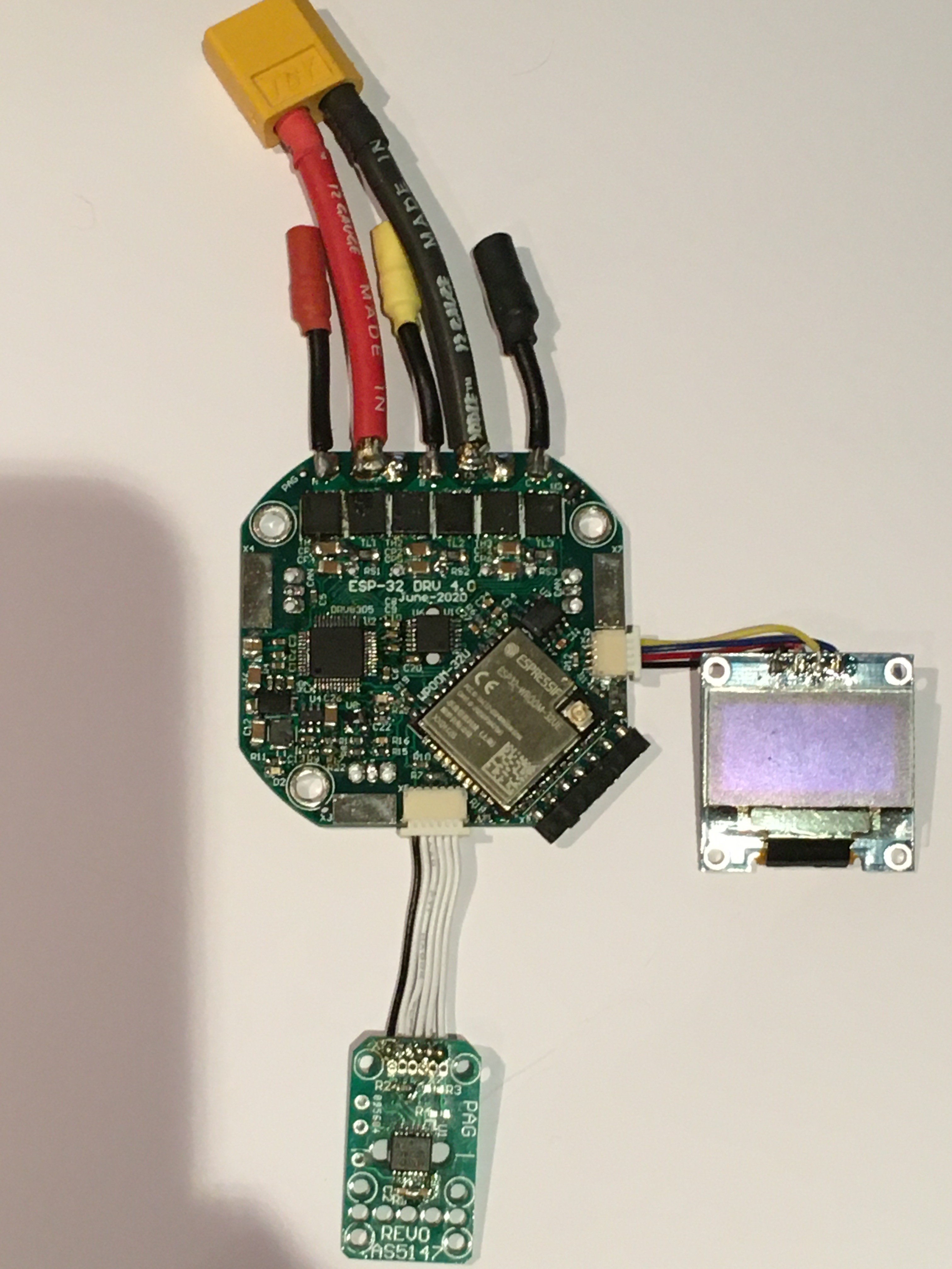
I can control a motor and a joint's position via bluetooth and display into on the I2C OLED (FET Temp, Battery Voltage, Joint Position, Motor current).
Has two absolute magnetic encoders, for for motor position and one for joint position
I do not recommend Bluetooth/wifi for joint control.
CAN is also up and running.
Discussions
Become a Hackaday.io Member
Create an account to leave a comment. Already have an account? Log In.