 M. Bindhammer
Self-tapping screws, M2 and M2.2, in various lengths are required for assembly. Holes in 3D printed parts are usually smaller than dimensioned. The drill holes can be re-cut with an appropriate drill bit. Additionally two spacers with a length of 6mm are needed. I use here pictures extracted from the 3-D drawing, because they are much clearer and easier to read than photos.
First the buttons for the tactile switch and the miniature joystick are attached and fixed with a drop of super glue. Here you have to be very careful not to let the superglue penetrate the switch housings, otherwise they are ruined and have to be replaced.
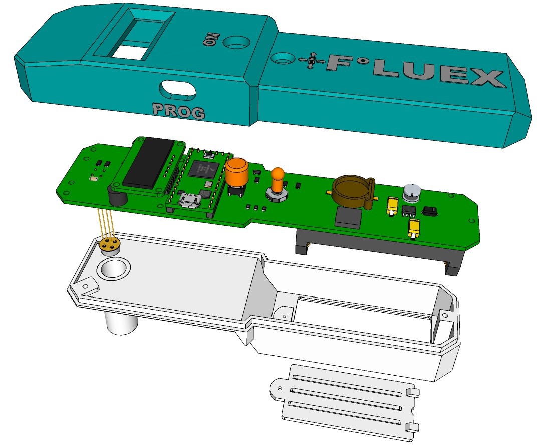
Next, the protective foil of the OLED display is removed and the board is screwed to the upper shell of the housing by using 2 M2x12 self-tapping screws. It is best to plug in the USB cable and check if the tactile switch can be operated easily before tightening the screws.

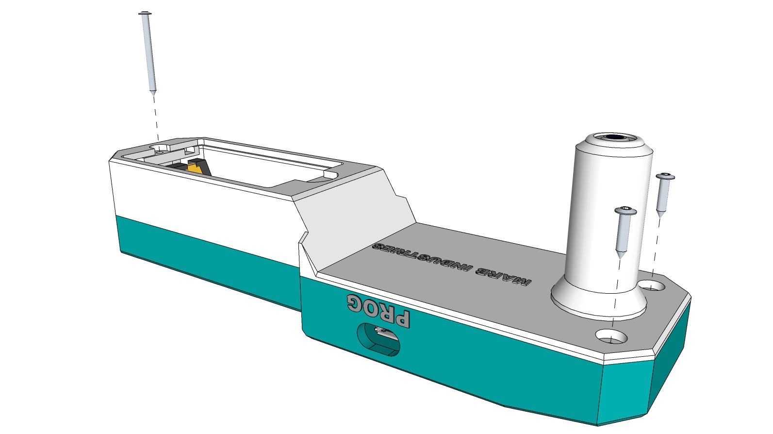
By using a self-tapping screw M2.2x25 and two M2x9.5 the upper shell of the housing is screwed to the lower shell.
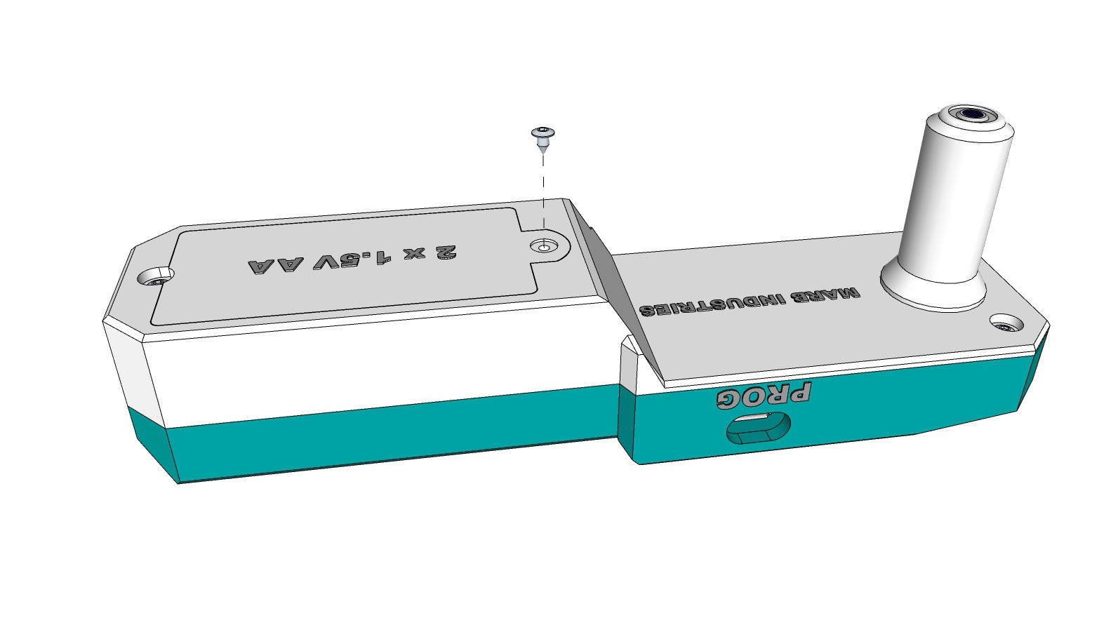
After the batteries are inserted, the cover of the battery box is fixed with a self-tapping screw M2x4.
Discussions
Become a Hackaday.io Member
Create an account to leave a comment. Already have an account? Log In.