 Jeff Cooper
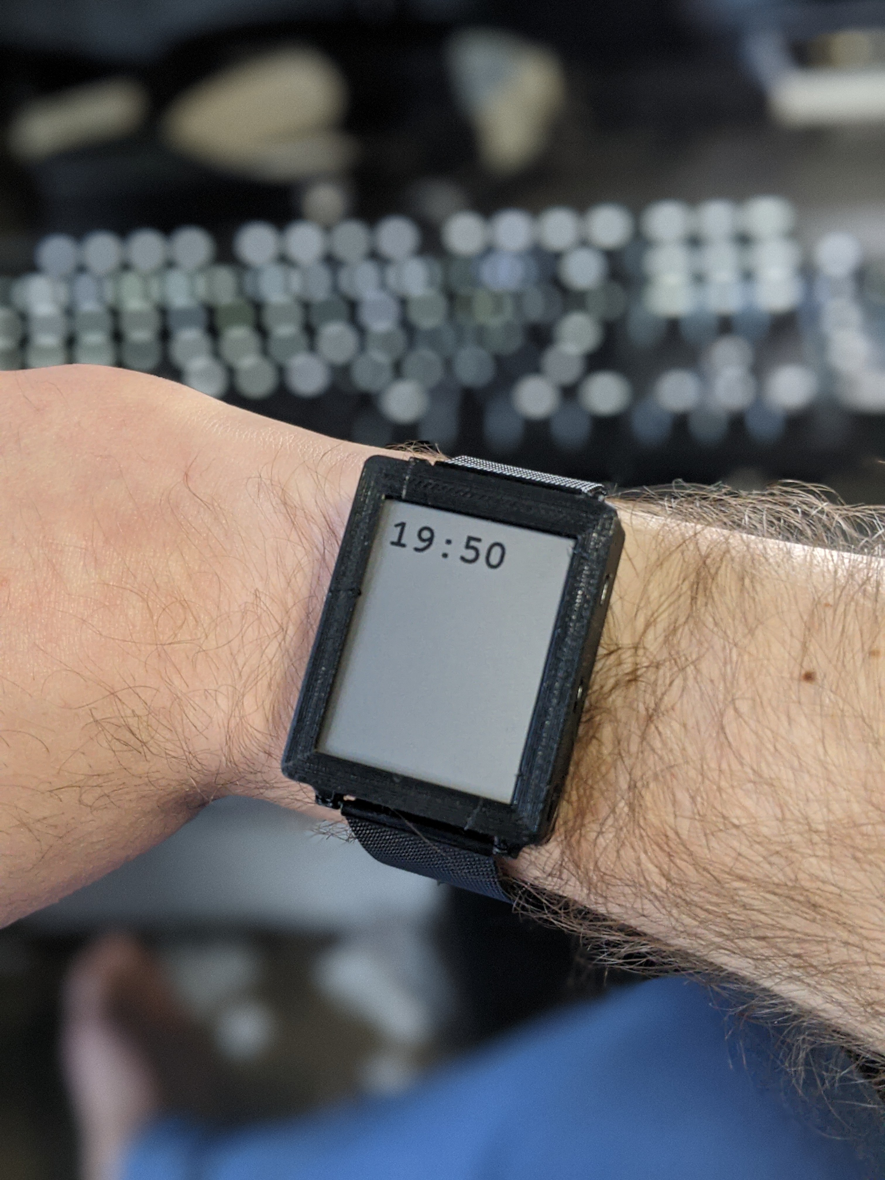
It's a watch! Revision 3 (technically 3.1, since I cancelled the rev3 order before it started production and made a tiny tweak) is here and assembled, and it's extremely wearable. It's astounding to me that for $20 USD I can have a circuit board custom-fabricated, flown halfway around the world, and in my hands in under a week. And that 75% of that cost is shipping!
Rev.3 is likely the last major revision for a while until the software is further along (though I might update the Flex PCB that holds the flashlight.. more on that below). Here's what it looks like out of the case:
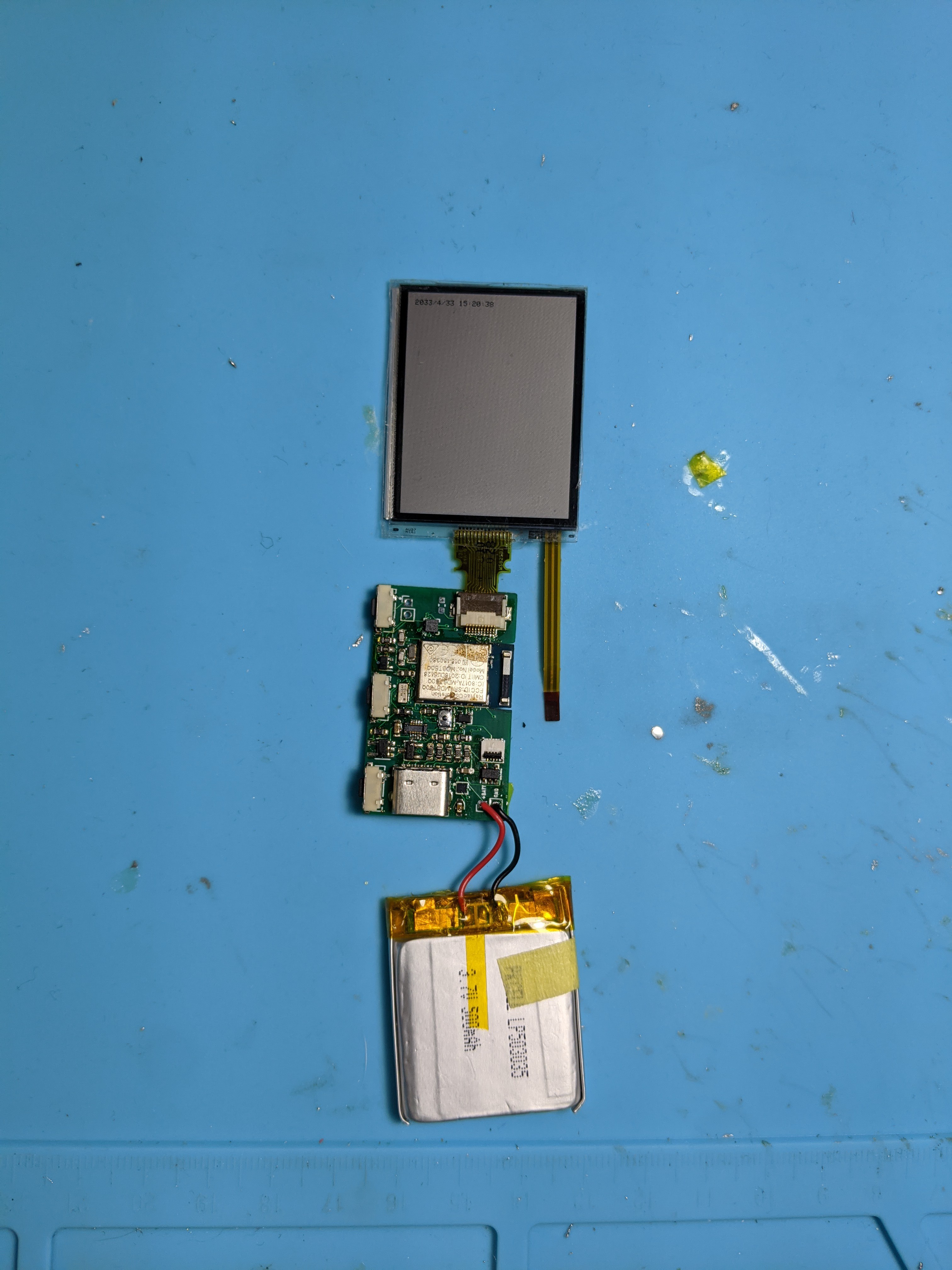
The ribbon cable hanging off the side of the screen attaches to the connector just above the battery, in the lower-right corner of the board. Overall, it was time-consuming to assemble, but not amazingly difficult. Keeping all of the components on the top side ended up being hugely helpful, since it meant that I could heat the board from below and not risk blowing any components out of position with my reflow gun.
I haven't fully tested everything, but here's what I do know:
- The frontlight circuitry works, though the protective film that I applied to the screen way back when makes the light hard to see. I may also need to lower the current-limiting resistor on that LED (it's currently 1k).
- The RTC works, and as long as I keep power connected, doesn't seem to have any issues.
- The accelerometer and fuel gauge enumerate on the i2c bus, but I haven't tested them beyond that
- The buttons seem to work. This isn't a surprise, but it's nice to know. I did set one of them to "reboot into bootloader mode," meaning that I don't have to have access to the reset switch to flash the watch. Eventually, this will be a menu option.
- I included circuitry to drive a small vibration motor, and since I had some lying around I threw one in. It didn't immediately work, but I don't know if that's because the the resistor value is wrong, the soldering is bad, or the pin mapping in code is wrong. I'm inclined to believe it's the resistor, but I haven't bothered to replace it with a smaller one.
- The flashlight (an XM-L2 flashlight LED) mounted on a flexible PCB is giving me some trouble. No matter what the input level is, the LED is always on. I've resoldered every piece along the path to no avail; my only remaining theory is that I accidentally shorted the GPIO that controls it to VIN at some point and I need to replace the MCU. Since that's a bit of a hassle, I haven't done it yet, but probably will tomorrow. The flashlight PCB worked fine with rev. 2, so I know the schematic is sound. I did have an interesting experience with the 3ohm current-limiting resistor getting hot enough to desolder itself at one point, so I've replaced it with a higher-valued one for the time being. It's still plenty bright. The only real problem with the layout at this point is that the mechanical position of the connector has changed, so the flashlight and buttons that go on that side of the watch are no longer centered on the watch body. A new revision of the PCB can fix that, but since it takes a few weeks to build, I'm going to print a case with the cutouts offset.
The next thing to do is to make proper mounts for the buttons in the case and print a new version. I may also sand+paint a version of the case so I have something presentable, since I have a family function coming up that I'd like to show off the watch at.
The next few updates are likely to be about software. I'll post the code and schematic soon too. In the meantime, some more glamor shots:
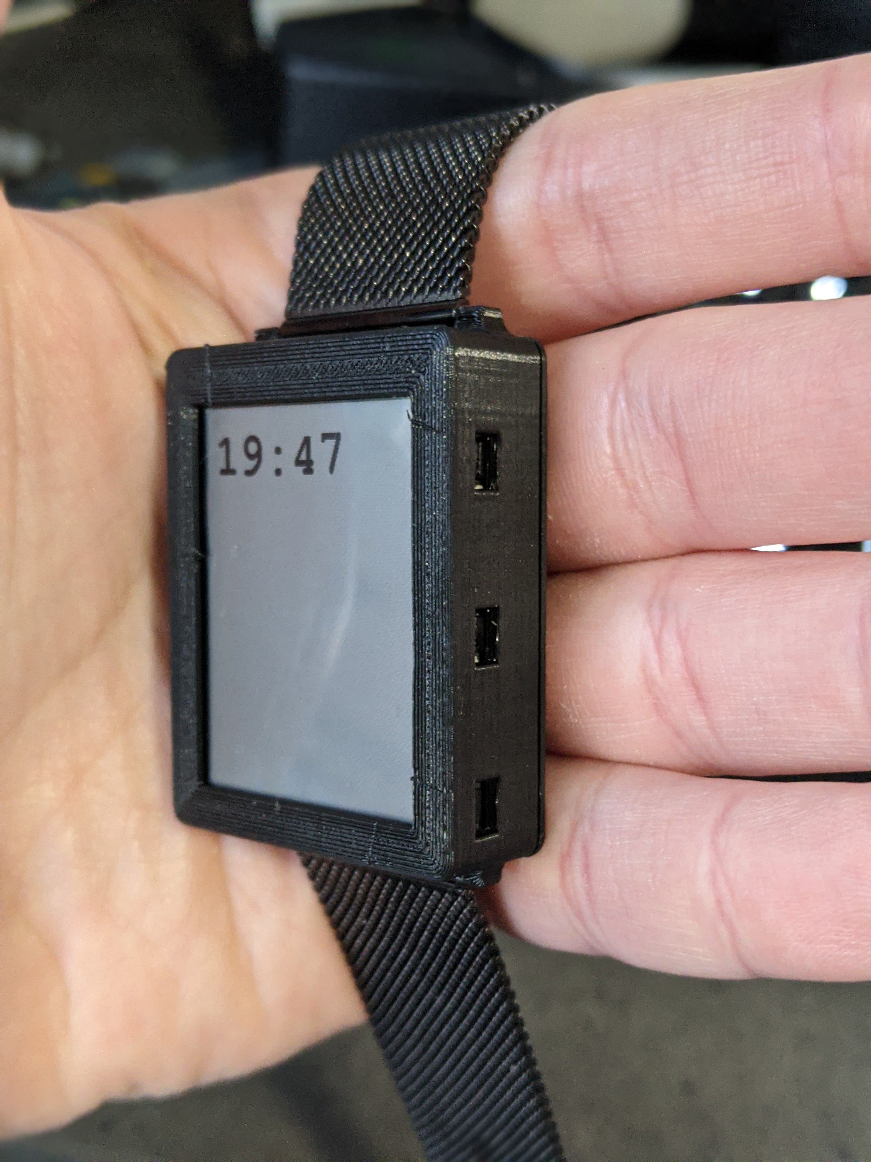
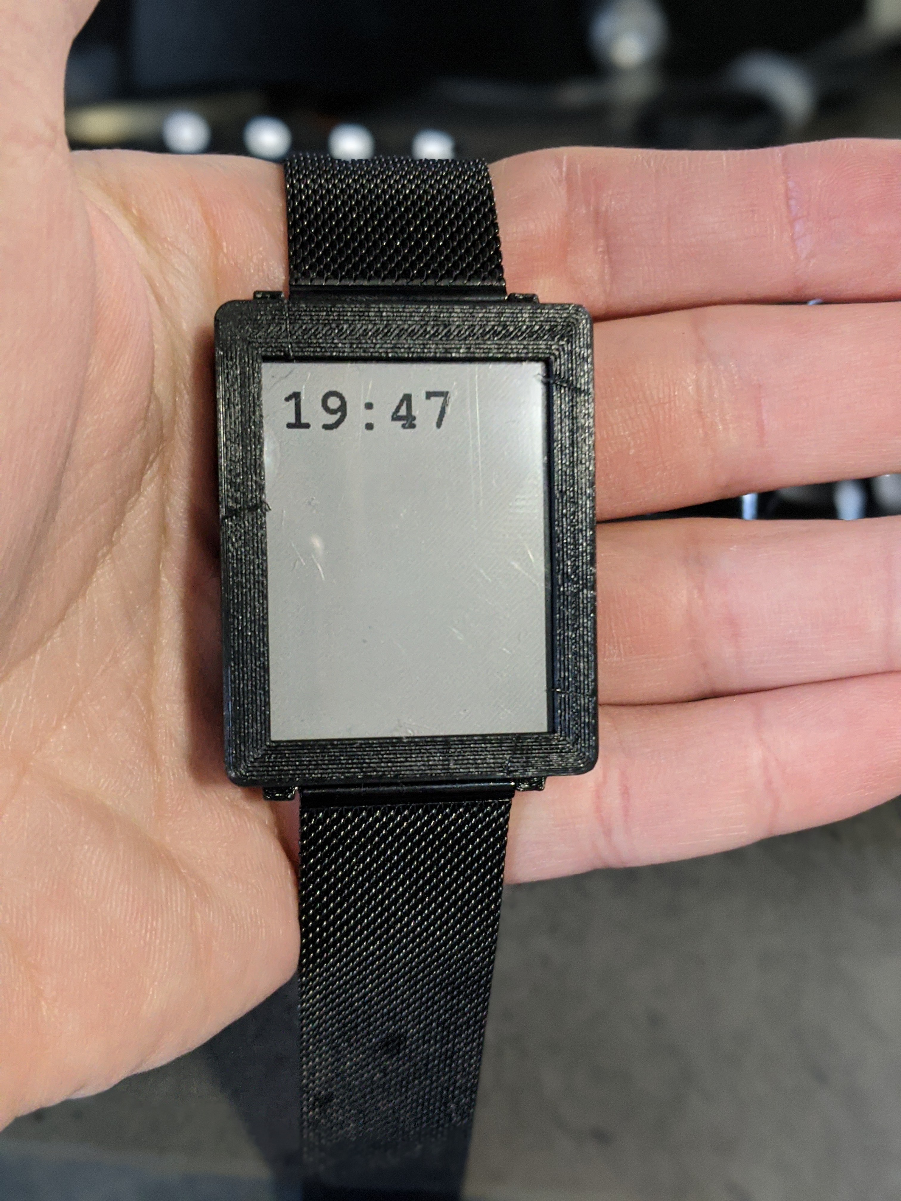
The case is designed to fit any standard 22mm watch band. The one attached in the picture is this one (note if you buy it: it doesn't come with pins!).
Discussions
Become a Hackaday.io Member
Create an account to leave a comment. Already have an account? Log In.
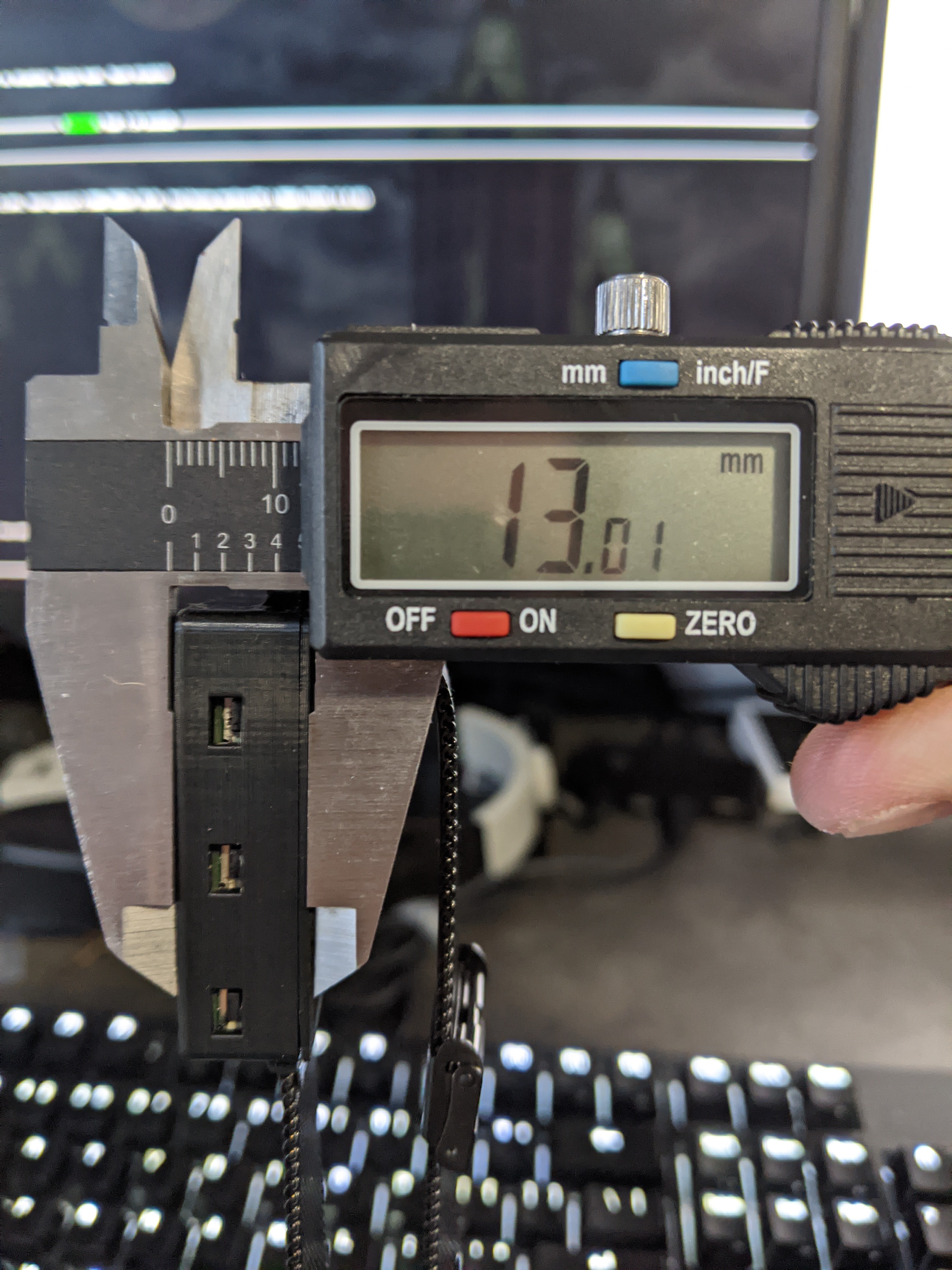
Awesome! I can't wait to see the software side of this project. Having the watch be only 13mm with a 3 layer stackup is pretty impressive. What kind of battery life are you expecting with that 500mAh battery?
Are you sure? yes | no
The theoretical target is to get consumption down to 500uA, which would give a battery life of 1000 hours (41 days). That makes a lot of optimistic assumptions, though, and says nothing of the flashlight/backlight usage, which will draw a fair amount of current.
Realistically, I'll be happy if I can get 3 weeks or more out of it. That's just shy of 1mA average current, which should hopefully be doable. We'll see though. After I get a basic UI done, I'm going to move over to power profiling to see how low I can get consumption.
Are you sure? yes | no
With that said, though, even 500uA is at least twice the theoretical minimum of what I would actually need if everything obeys its datasheet... so we'll see.
Are you sure? yes | no
Another thing worth noting (and sorry for the string of comments) is that the stackup is only sort of 3 layers. The PCB nests neatly against the LCD's backlight module, so those two layers together are only barely thicker than the LCD on its own. I had the PCB fabricated at 0.8mm thickness rather than the standard 1.6mm (JLC didn't charge any extra, which was nice). Aside from the time I nearly snapped it in my board vise, that hasn't caused any issues.
Are you sure? yes | no