 Dan Maloney
![]() Does that not come ith experience Charlie ... ?
Does that not come ith experience Charlie ... ?
 I don't mind using other peoples circuits, but I need to understand how they work forst.
![]() That would be amazing.
That would be amazing.
MS-BOSS. That's true, but good for 80m-40m I suspect.
![]() Its informative to take a cap or an L and to try measuring it and understanding it - specially with more than one meter
Its informative to take a cap or an L and to try measuring it and understanding it - specially with more than one meter
![]() Some older radios have the area's marked out with white lines and labels. So its easier to figrue out what does what.
Some older radios have the area's marked out with white lines and labels. So its easier to figrue out what does what.
What's that Juggle?
![]() understanding a circuit properly
understanding a circuit properly
![]() yeah, i'd like to see some well documented impedance matching amplifiers that don't need transformers, like an IF amp that matches 50 ohm out of a mixer to 500 ohm crystal filter
yeah, i'd like to see some well documented impedance matching amplifiers that don't need transformers, like an IF amp that matches 50 ohm out of a mixer to 500 ohm crystal filter
 Anybody has experience in getting CE /FCC for radio module?
Yes. A lot of the HF manuals explain the circuit quite well.
 SPICE is your friend, especially if you can get S-parameters of components as well as transient model.
Juggle. Yes. I had a good foundation through the air force. The more you do the more you understand how the circuit works.
 @David I need to read into the latest and greatest. I'm a decade or two behind... spent most my time on FTNIR et.al. Interesting what can be made with lab test equipment also and with and for less now days.
 That's what I actually like best about Charlie's videos: here's the component, this is what it does, and here are the calculations that I used to figure out the value. Great stuff
![]() @Tomi Piriyev I ran a few RF modules through FCC.
@Tomi Piriyev I ran a few RF modules through FCC.
 @Tomi Piriyev I suspect there probably isn't much experience with that here since the focus is homebrew which wouldn't require testing and cert
Again, my approach is to keep tings simple. I'm trying to provide a resource back to the community.
![]() @Charlie Morris ZL2CTM - would David Rutledge's "The Electronics of Radio" fall into that for you? I think it is basically walking through the design of a Norcal 40.
@Charlie Morris ZL2CTM - would David Rutledge's "The Electronics of Radio" fall into that for you? I think it is basically walking through the design of a Norcal 40.
![]() Yes, especially as a beginner, it's not like I know that measuring that component is gonna show me xyz. it's nice being able to read through (or watch) someone's thought process and why they landed on designing something a certain way
Yes, especially as a beginner, it's not like I know that measuring that component is gonna show me xyz. it's nice being able to read through (or watch) someone's thought process and why they landed on designing something a certain way
I hope I do that June. That's the aim.
I know the radios are simple and not 'contest grade' but that's the point for me.
I'ver a got a CW rig on the go here.
![]() Contests are great test grounds for simple xmtrs :-).
Contests are great test grounds for simple xmtrs :-).
@Gary Sutcliffe i would like to get CE/FCC certification for my Lora module
@Gary Sutcliffe i am wondering how long does it take and what price range?
 @James Finch https://pubmed.ncbi.nlm.nih.gov/28043004/
I'll build the receiver first and check out that HB filter
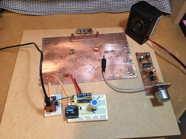
![]() you can't beat bare copper and a hot soldering iron !!
you can't beat bare copper and a hot soldering iron !!
![]() I need to get a better soldering iron. I can't get mine hot enough to solder to a bare copper panel.
I need to get a better soldering iron. I can't get mine hot enough to solder to a bare copper panel.
![]() use pads or me-squares
use pads or me-squares
@James Finch there also nice paper on non-resonant amplifier and antenna design I could try and find for you
TIme wise is hard to say. You can easily knock out an amp in an evening. Cost is not too bad either, especially with AliExpress. Probably well under $100
 @KD9KCK pre-heat it
![]() Hm use islands. Good idea.
Hm use islands. Good idea.
![]() old fashioned bread boarding at its finest -
old fashioned bread boarding at its finest -
![]() @Charlie Morris ZL2CTM - how much "stuff" do you have on hand vs ordering things for a project you have in mind?
@Charlie Morris ZL2CTM - how much "stuff" do you have on hand vs ordering things for a project you have in mind?
I have a nice Weller one here. Having a good tip is important too.
Those cheap ~$10 LCR-T4 Mega meters are nice to getting started for testing and matching components.
@KD9KCK put the pcb on an electric grill
![]() put a pad on the intersections of every wire on Charlies design and you're away :-)
put a pad on the intersections of every wire on Charlies design and you're away :-)
![]() Mines an old RadioShack 30 watt iron.
Mines an old RadioShack 30 watt iron.
The copper board as a base works well for me. I have very few instability probs.
![]() super glue the pads and you can pop them off with a sharp blade later
super glue the pads and you can pop them off with a sharp blade later
James. Yes. You don't need lab grade equip to get going.
![]() my next project (after an antenna) was gonna be a cw single paddle with copperclad pcb as the main parts... y'all making me think i should get a different soldering iron (ive never used copperclad pcb before)
my next project (after an antenna) was gonna be a cw single paddle with copperclad pcb as the main parts... y'all making me think i should get a different soldering iron (ive never used copperclad pcb before)
Super glue is very funny once you heat it up and get the nasty fumes in eyes.
![]() easy to see and tweak too and as Charlie says - stable
easy to see and tweak too and as Charlie says - stable
![]() keep the glue the other side of the pad
keep the glue the other side of the pad
I had a simple (I htink) 30MHz scope. The LCR meter is an M4070
![]() hot iron, small pad, fast joint glue stays cool
hot iron, small pad, fast joint glue stays cool
I also sandpaper down old copper boards and use them again. As per the photo.
The M4070 is OK, however lacks the possibility to select test frequency.
@David Sure, thanks for the link. Great to see... interesting what can be analyzed using the RF range under the right conditions.
Agreed.
![]() I second having a good solder tip. Use a brass sponge to clean them instead of a wet sponge so your tip lasts longer.
I second having a good solder tip. Use a brass sponge to clean them instead of a wet sponge so your tip lasts longer.
If you've got a non-temp controlled iran, do yourself a favor and pickup an inexpensive one...there are Hakko knockoffs on aliexpress/ebay which work with genuine Hakko tips and they are probably $20 or so
A sponge for washing dishes and a bit of detergent does the same job without peeling of as much copper.
![]() A paper towel doesn't peel copper or reduce the tip temperature.
A paper towel doesn't peel copper or reduce the tip temperature.
Anyone have a BITX?
![]() yup
yup
I have a uBitx
That's another way to get into HF.
I use it for SOTA
![]() yeah, the $40 898 with hotair and temp solder is pretty good for $40
yeah, the $40 898 with hotair and temp solder is pretty good for $40
![]() yep, two of them
yep, two of them
![]() I was thinking of getting a uBitx. Looks like it would be a nice radio.
I was thinking of getting a uBitx. Looks like it would be a nice radio.
I think they are good platform to experiment with. Not too expensive.
![]() Charlie, you're a rare beast, you build AND operate, many do one or the other !!
Charlie, you're a rare beast, you build AND operate, many do one or the other !!
I also think a DSB DC rig is a good starting point too. I started with that and then went to SSB.
it's an ok radio but it's open hardware and quite hackable...you'll prob want to add RF chokes to the digital lines, replace the pot and encoder, and add an AGC circuit
No point biting off too much at the beginning and getting frustrated.
I also modified mine to add a LiPo charge controller (pre-built) so I can perm install batteries for outdoor operation
That it Trevor. Buy the base radio and hack it. That way you will start to learn what is going on.
![]() my ubitx has all sorts of wires and bodge solders going on now. but i pretty much quit using it after buying an old kenwood at a hamfest
my ubitx has all sorts of wires and bodge solders going on now. but i pretty much quit using it after buying an old kenwood at a hamfest
![]() Charlie, I really like your design and build technique, out in the open where eveny thing can be seen.
Charlie, I really like your design and build technique, out in the open where eveny thing can be seen.
![]() thats the other cheap easy way in - old kit from rallies etc
thats the other cheap easy way in - old kit from rallies etc
Juggie. I probably build more than operate. I like tramping/hiking so making small radios is enjoyable.
![]() hence the light waterproof form factor I guess
hence the light waterproof form factor I guess
I'll upload a pic soon.
 |}{|
|}{|
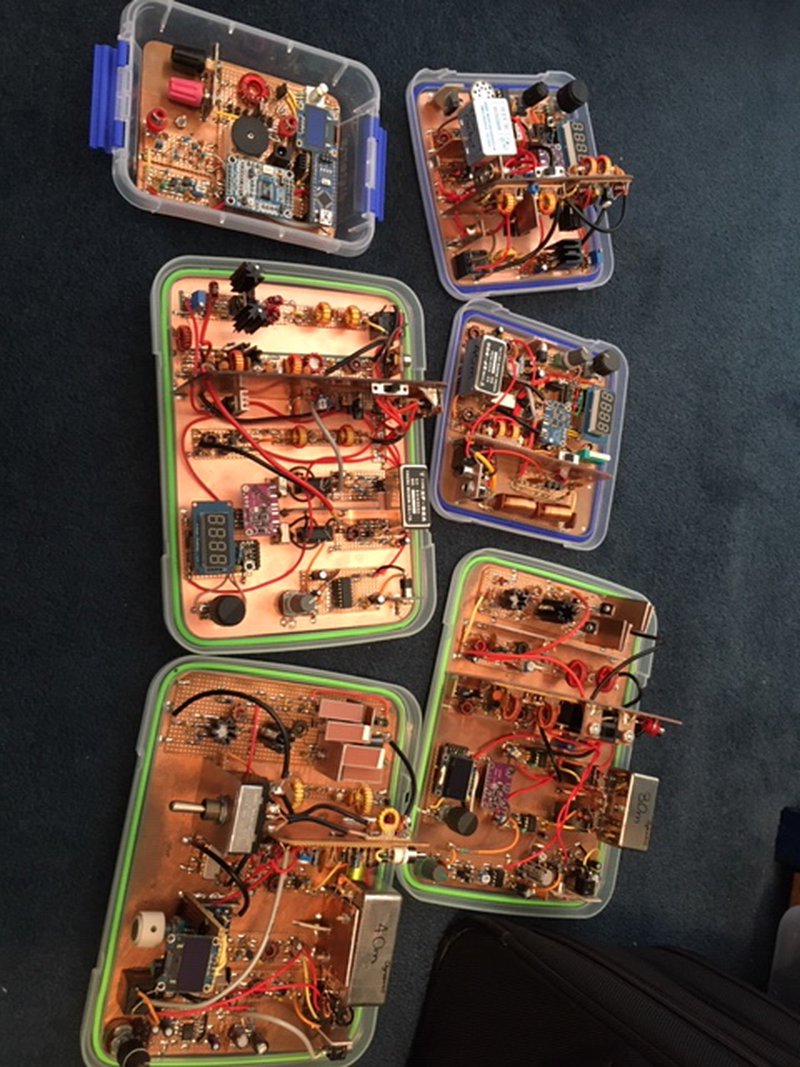
These are all built in plastic boxes.
![]() Are those tupperware lids?
Are those tupperware lids?
So many food containers...
![]() Awesome!
Awesome!
![]() The vertical copper pieces - are those to isolate signals, or to fit more in the space?
The vertical copper pieces - are those to isolate signals, or to fit more in the space?
It's a local brand herem but essentially the same.
They are built into the lids. The bottom is only attached for transport.
I think the fine tuning of lab test equipment is what inspired me to just use that gear until I wanted smaller form factors for mobile and HT use. The price and noise floor of spectrum analyzers has me focused on building those.
![]() Very nice pieces of kit!
Very nice pieces of kit!
Both. Thet separate the TX and RX and provide more room to mount boards.
![]() Do you find you need the TX/RX separation? (ie, do you notice if that isn't there?)
Do you find you need the TX/RX separation? (ie, do you notice if that isn't there?)
Hardcore kit porn! Awesome!
![]() So far all my homebrew has the TX and RX are separated because it is spread all across the workbench
So far all my homebrew has the TX and RX are separated because it is spread all across the workbench
![]() hi
hi
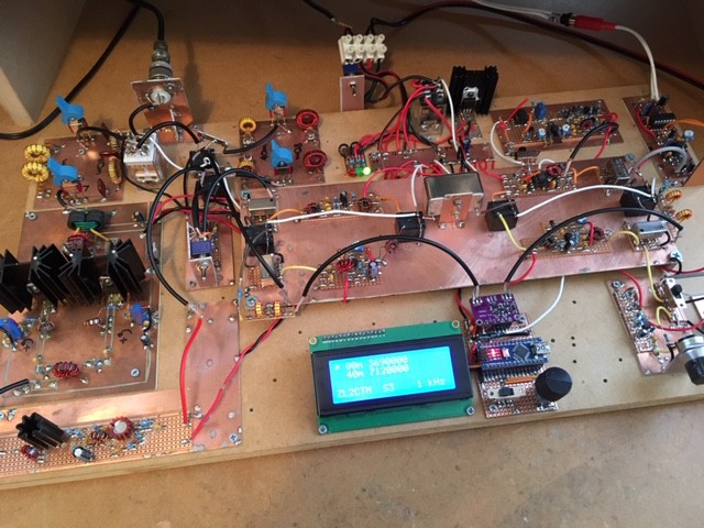
I just do it. My approach is always to separate the high power TX rx from earlier amp stages. Less likely to have onscillations/instability.
I have had that on the base rigs.
The stripboard works well too for me.
![]() I like the modular approach but with it on one board - less chance of ground loops
I like the modular approach but with it on one board - less chance of ground loops
Here's another one
Anyone using the Si4432 or thoughts regarding? They're so cost effective: https://www.ebay.com/itm/1PCS-Mini-SI4432-Remote-Wireless-Transceiver-Communication-Module-240MHZ-930MHZ/183413464917
![]() Real Ham Radio!
Real Ham Radio!
Again. Build each stage individually and test it. Then combine then.
![]() where do you put all your mdf boards with radios on them? :)
where do you put all your mdf boards with radios on them? :)
When breadboard were breadboards!
That way you get the satisfaction that everything is on track.
![]() reusable modules for later raios ...
reusable modules for later raios ...
@James Finch Have a look at the 128 registers you need to configure before you can use the radio.
bIOOp. Yes, on a shelf next to the desk. I can count three up there.
![]() I use the back side of floor planking - good size and stiff
I use the back side of floor planking - good size and stiff
I do reuse some stages, but more often than not I simply reuse the componts.
![]() Also, build the fittings jto support the pots, caps and switches using a 3d printer
Also, build the fittings jto support the pots, caps and switches using a 3d printer
Discussions
Become a Hackaday.io Member
Create an account to leave a comment. Already have an account? Log In.