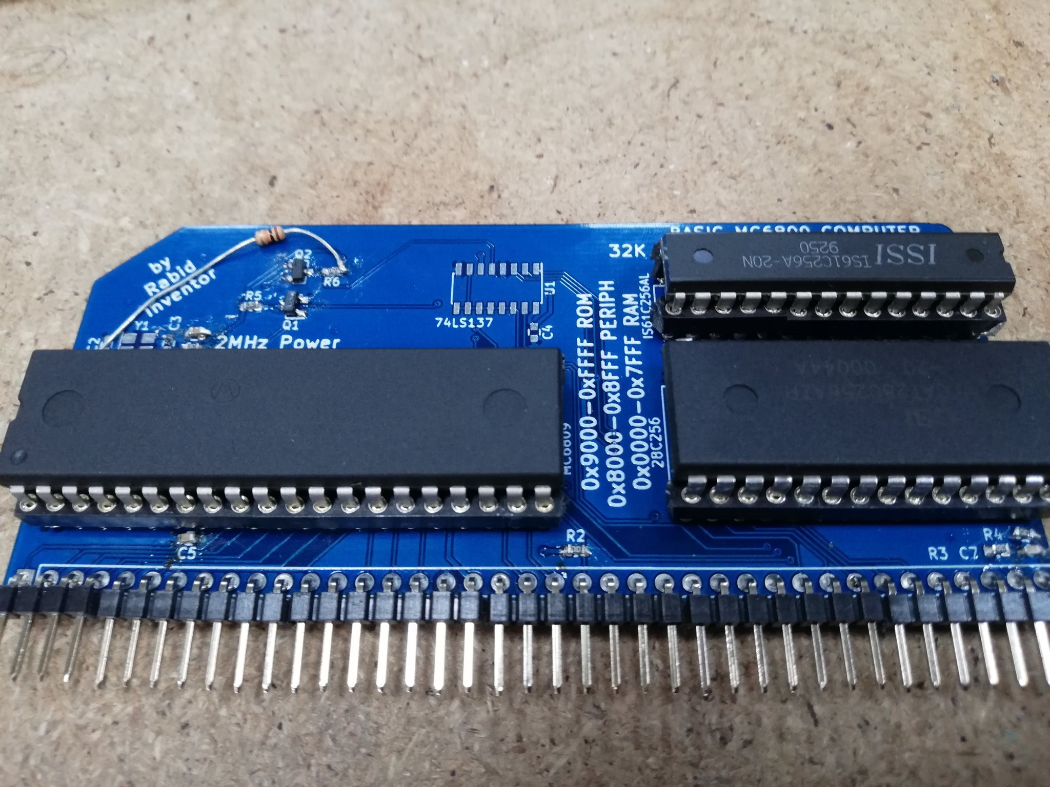
I managed to build one of the REV1 boards and have been spending some time on an off working out all the kinks before going to the next version.

i decided not to puth the decade counter on for the moment though that will be something i will come back too.
I also found some issues when it came down to the pulling of certain pins.
Out of habit i had already added pull-up resistors to the interrupt pins to try and keep them stable aslos the same situation with the reset pin.
Soon after I found out that the reset pin has no internal pull-up resistor either so that is the reason for the resistor that can be seen in the above image.
The other issue was the when the device was free running it would swap between different speeds. A0 was jumping between pulsing at 100KHz and 10kHz and when i touched the back of the board in a certain way it would stabilize.
After a little further investigation I discovered the DMA request pin didn't like being left floating as it would issue a dma request which cause the Processor to release the address and data bus for up to 16 cycles.
The final fault that i am still trying to thrash out before moving forward is running from a xtal so far the only way i have had the chip running is a buy using an arduino to generate the clock signal.
As you can see in the above video the processor is free-running and showing the output form A15 and A13. which give a 1:4 flash pattern. It easy to also see where the clock signal is patched in.
Last thing to check is can it execute instructions from ROM and can it store values in RAM once these are tested I can move forward with REV2
 Gee Bartlett
Discussions
Become a Hackaday.io Member
Create an account to leave a comment. Already have an account? Log In.