Michael Gardi
-
Tic-Toc, Click-Clack, and Blinkenlights Too
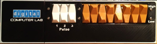
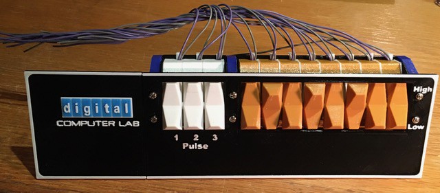
05/08/2020 at 16:44 • 0 commentsAll of the active controls for the H-500 are located in the lower part of the device.
![]()
These included (taken directly from the Computer Lab Workbook):
- Rocker Switches - Rocker switches can be used to provide either a HI or a LO logic level. If the upper side of the rocker switch is depressed, the two corresponding switch output terminals (directly in front of the switch) are taken to a HI level. If the lower side of the switch is depressed, the two corresponding output terminals are taken to a LO level.
- Pulser Switches - The outputs of the pulser switches are normally LO. When a pulser is depressed, the corresponding two terminal terminals go to a HI level. When the pulser is released its output terminals return to the LO condition. Internal circuits connected to the pulsers make sure that when a pulser is depressed or released, electrical noise generated in the switch is not transmitted to the pulser output. This special circuitry makes the pulsers useful in applications requiring noise-free transitions from one level to another. Rocker switches do not have this feature.
- Clock - The clock provides a continuous train of HI pulses. Clock pulses are 50 nanoseconds wide. The frequency of clock pulses can be continuously varied from less than one pulse per second to over 10 million pulses per second. The slowest range of the clock is obtained by connecting the common clock coarse terminal to the left-most speed-selecting terminal. The repetition rate of the clock increases with each terminal to the right. The fastest repetition rate is obtained by leaving the clock range selector disconnected. Repetition rates within each coarse range can be varied using the clock fine control. (Fully counterclockwise gives the slowest repetition rate; fully clockwise provides the fastest rate.) The clock range coarse terminals are to be used only for selection of clock repetition rate. The clock output is obtained from the two terminals labeled CLOCK OUTPUT.
- Lamp Indicators - The operation of experiments constructed on the COMPUTER LAB patchpanel is monitored by the lamp indicators. A lamp will be ON if its corresponding input is at a HI logic level. A lamp will be OFF if its corresponding input is at a LO logic level. If no connection is provided to a lamp, the lamp will be OFF. Lamps will respond to sustained logic levels and pulses of sufficient duration to activate the lamp filament.
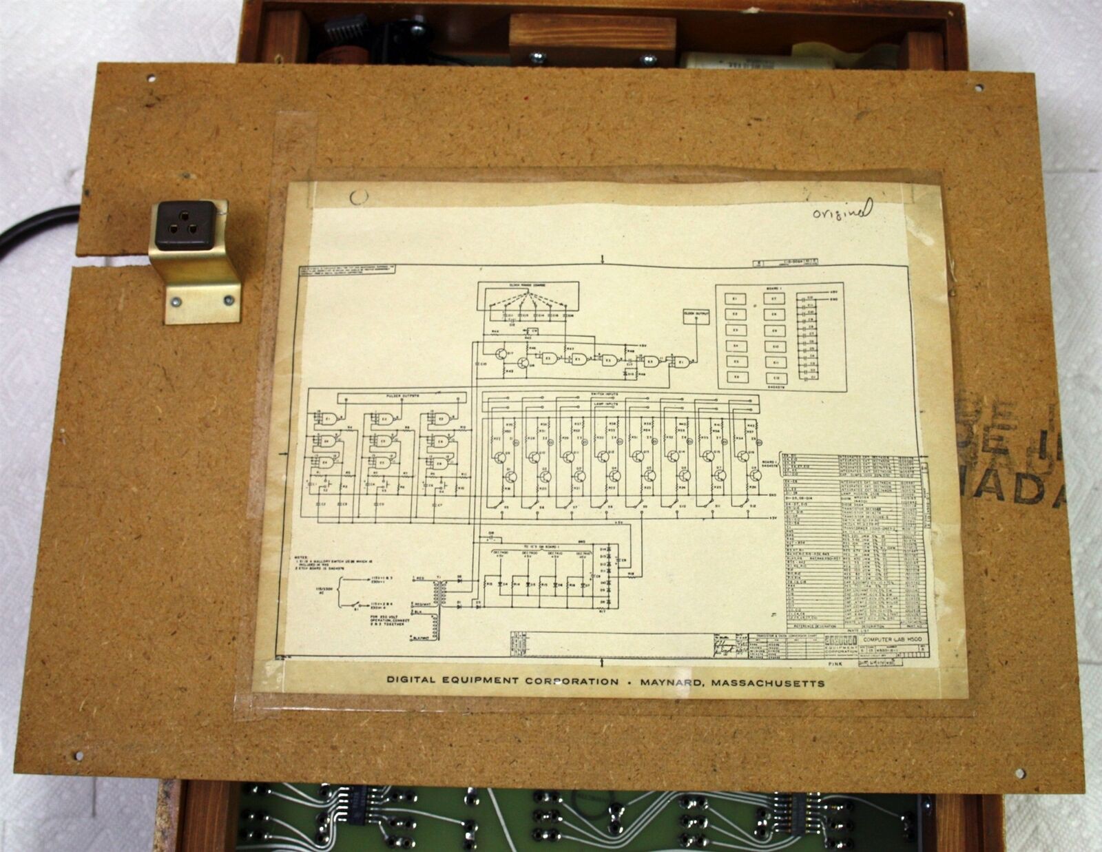
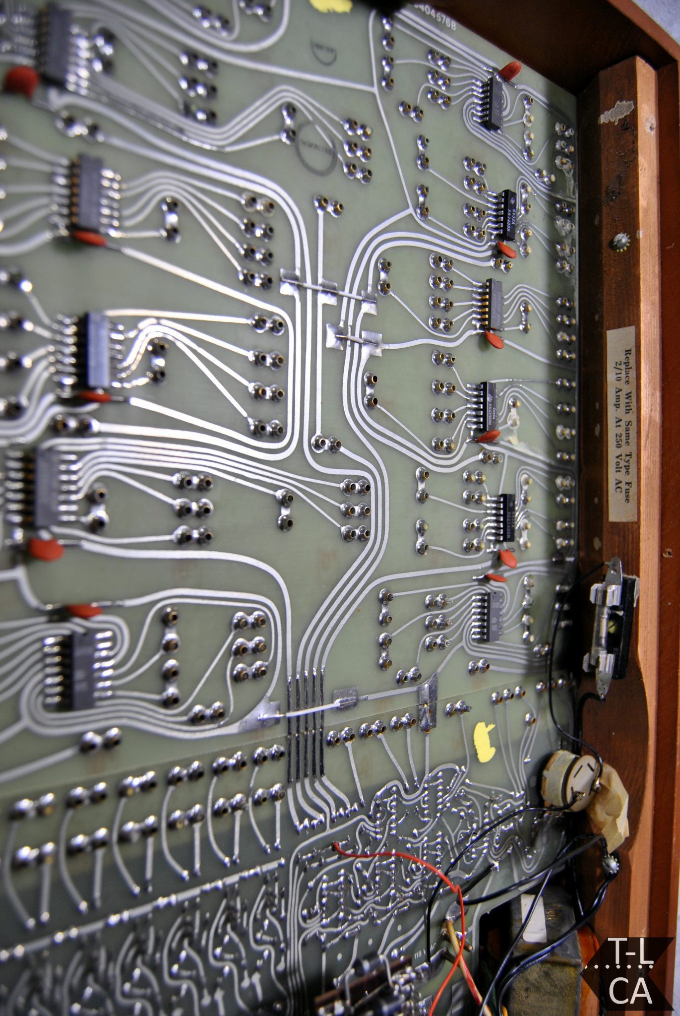
So how were these functions implemented back in the late 60's. Like this:
![]()
I apologize for the image quality. I'm trying to find a better photo. Looks like this schematic was taped to the back of the frame's rear cover.
Now I'm not going to pretend that I completely understand all of what is going on in this schematic. Electronics is not my strong suit, I'm more of a digital guy. (if anyone wants to help me out here with a short description of what the above circuit does I would be happy to include it in the write-up.) Suffice it to say that the complexity of reproducing this circuit goes counter to two of my primary design goals with this project: make it easy to reproduce and not too expensive.
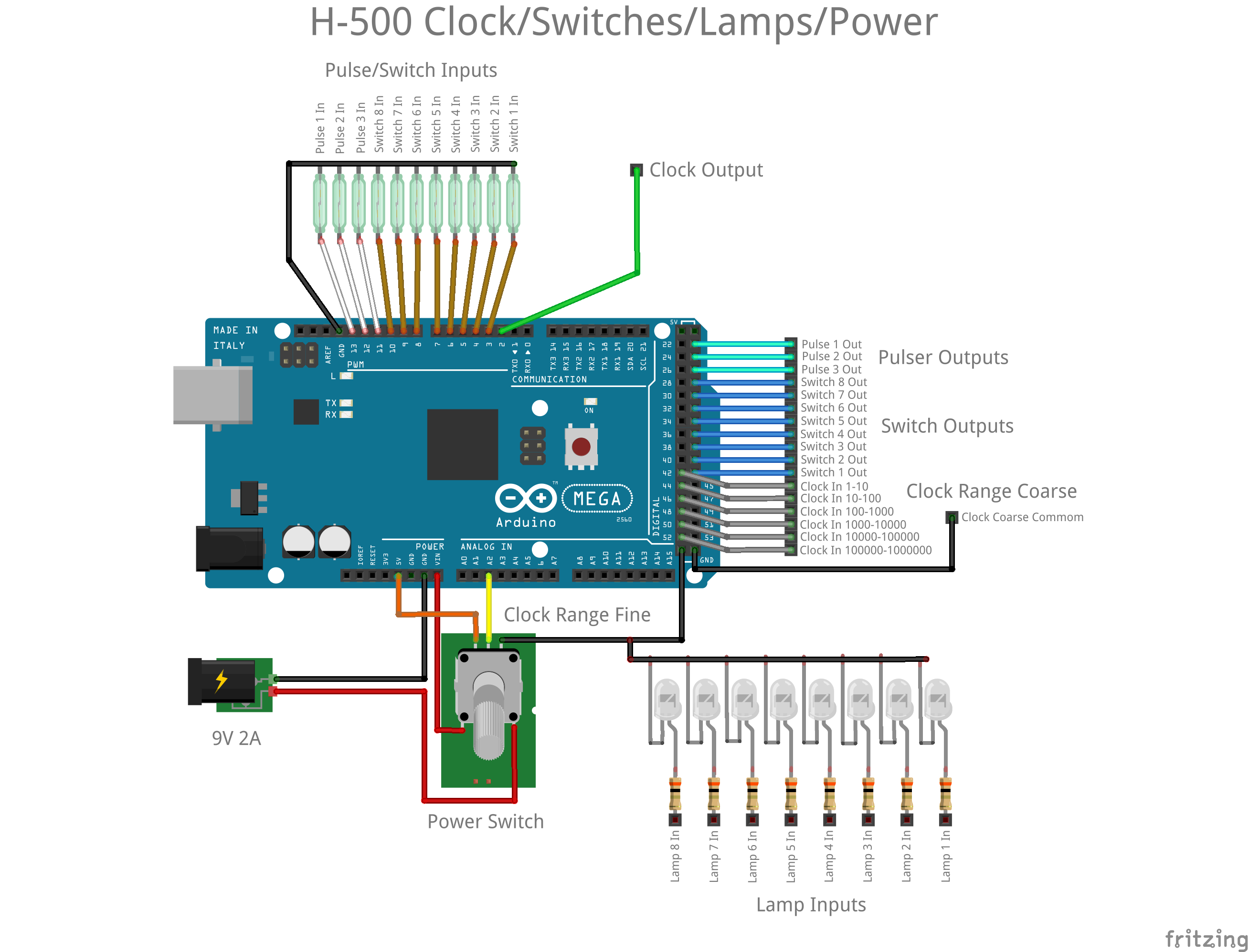
Fortunately I do know what the circuit is supposed to do. So what would be an easy and cheap replacement, well understood by today's community of makers, well an Arduino of course. This is what I came up with:
![]()
Rocker and Pulser Switches - The magnetic reeds of the rocker and pulse switches are monitored by eleven inputs that are set with their pull-ups enabled. When the normally open reed switch is "activated" by a magnet its input line will be pulled down. The Arduino sketch monitors changes to the reed switches and will only change the state of it's corresponding output line once the switch has been suitably debounced (three consecutive reads 20 milliseconds apart with the same state). In this implementation all switches are debounced, not just the pulsers. We are already at 22 I/O lines so it's a good thing that the Arduino I had lying around was a MEGA 2560.
Clock - Six more inputs with pull-ups enabled were dedicated to monitoring the clock range coarse jumpers. The clock frequency ranges that each enables can be seen on the diagram above. Ranges are checked from lowest to highest, stopping at the first one found to be enabled with a jumper. Also the potentiometer is read via an analog in line and converted to ten steps (1-10) and applied as a multiplier to the lowest value in the selected range. So if the clock range set is 10-100, as the potentiometer is turned clockwise, the clock frequencies will be changed to 10, 20, 30, ..., 100 clocks per second. If no coarse range jumper is set, I leave the clock frequency fixed at one clock per second. Clock pulses are emitted via a digital output line.
Lamp Indicators - Included in this diagram for completeness, the lamp inputs are not processed by the Arduino in any way. Just apply a Hi signal and they will turn on.
Power - A switched potentiometer is used to turn the device on and off as with the original.
Using an Arduino is not without some compromises. First of all I'm using the excellent TimerOne library to implement interrupt driven clock pulses. It tops out at about 1,000,000 interrupts per second, so that's my maximum frequency as well, 1,000,000 clocks per second. On a similar note the clock pulse itself is generated using the digitalWriteFast library. Within the clock interrupt the code is simply:
digitalWriteFast(2, HIGH);
digitakWriteFast(2, LOW);
According to the documentation the digitalWriteFast() "call" takes about 125 nanoseconds to execute. So that means that the clock duration will be somewhere between 125 and 250 nanoseconds. (I'll know more precisely when I can get back into my maker space (kwartzlab) and access a scope.) A little more than the 50 nanosecond duration the original could produce, but I think it will be adequate for my purposes.
I know that I will probably get some feedback for using a "microprocessor" in this project. If were trying for a more authentic replica I would totally agree. However in this case, where I and am shooting for more of an H-500 Computer Lab working reproduction, the Arduino allows me to simply replace a bunch of discrete components with a cheaper, faster (at least for me), easier, better understood solution.
I've added my Arduino sketch to the Files section of this project. It's not pretty but gets the job done.
-
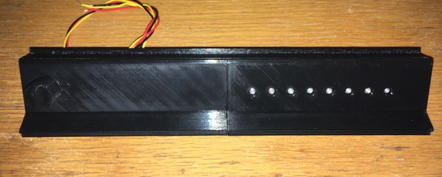
Light Panel
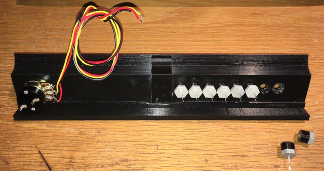
04/28/2020 at 14:45 • 0 comments![]()
This piece separates the Switch Panel from the Plug Panel, holds the eight output lamps and the fine tuning knob for the clock speed, and also transitions from the higher switch level to the lower plug level within the wooden frame.
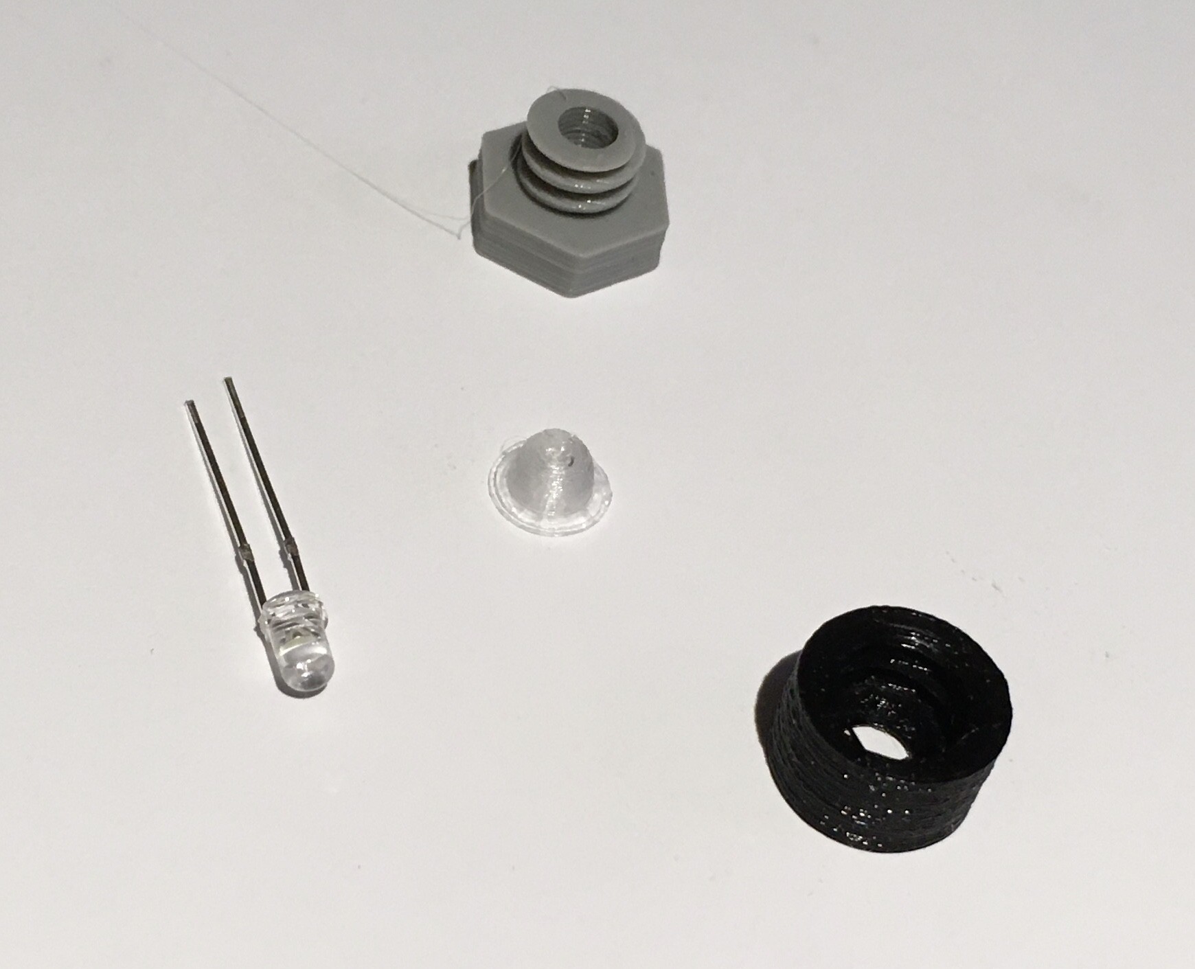
It's impossible to know from just pictures what kind of bulbs they used in the original, but if I had to guess based on the estimated size (about 4 mm) I would say grain of wheat bulbs. I could have ordered some but given the current lead times for delivery of non-essential items I decided to go with what I had on hand, LEDs. I modified my Panel Mounted LED Socket by adding a 4 mm diffuser printed with transparent filament.
![]()
When put together it looks like this.
![]()
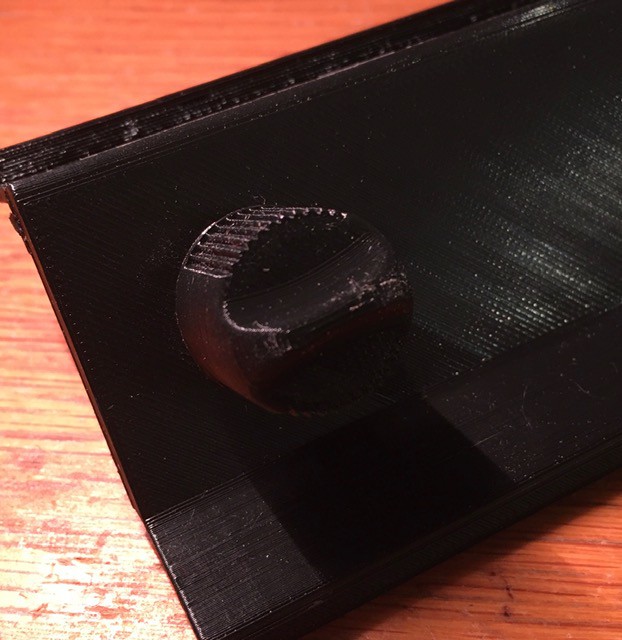
These bulb assemblies were slotted into holes on the back of the Light Panel. The panel itself was printed in two pieces and glued together with the aid of a reinforcing strip. You can see the clock fine adjustment potentiometer mounted on the back as well.
![]()
From the front here is the fine tuning knob that I modeled...
![]()
... based on the original.
![]()
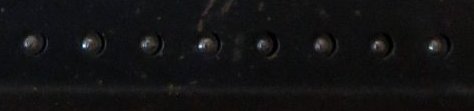
The "bulbs" ended up looking pretty good. I found that I will have to add a 4K limiting resister to each LED to get the brightness down to incandescent levels.
![]()
![]()
The light panel is ready to go.
Updated May 7, 2020: Last week Bob Roswell, curator of the System Source Computer Museum, was kind enough to spend some time on the phone with me talking about the H-500 that they have on display. He also provided me with some invaluable first hand measurements and some close-up pictures. While my light panel was pretty close to the original measurement wise, I had learned that the potentiometer on the original was also the power switch so I redid the panel to fine tune the measurements and accommodate the new pot with switch. The photo of the tuning knob Bob provided also allowed me to produce a more accurate replica. Thanks Bob. I have update some of the pictures above with the new parts.
-
Switch Panel
04/24/2020 at 22:01 • 2 commentsWith all preparations complete I forged ahead and built the bottom part of the H-500.
![]()
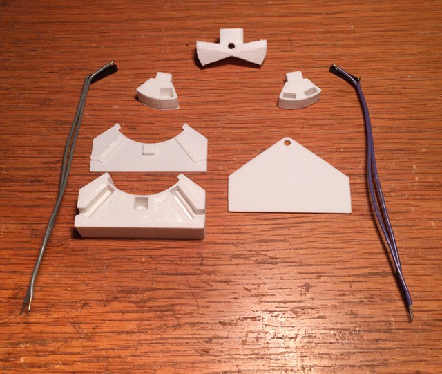
Here is what I did. I started by preparing the eleven rocker switches required, three momentary "spring" return types for the H-500 pulse switches, and eight ON-ON variants for the input switches. I took care and made sure that the magnets were all oriented the same way and used my 3D pen to secure them in place. See Rocker Man for details.
![]()
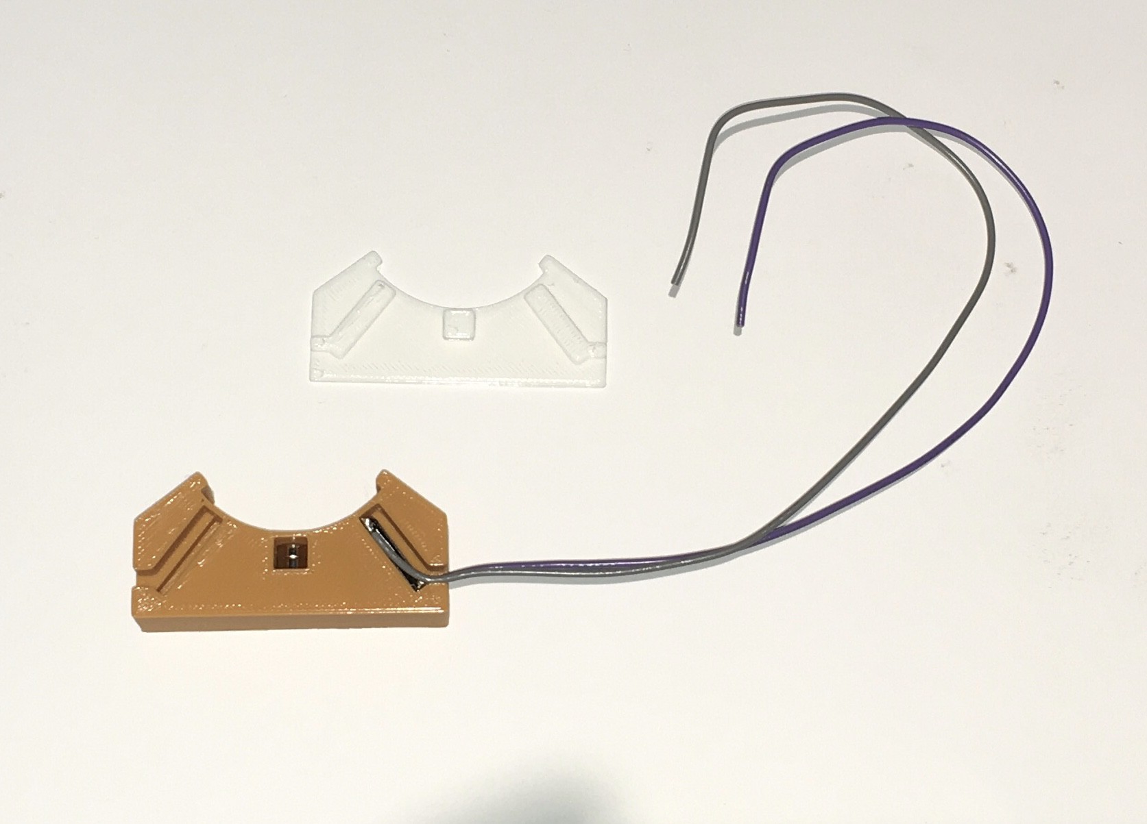
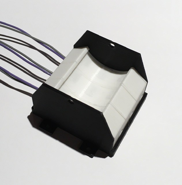
Next I prepared the eleven rocker switch bases. They are all the same as the one below. You will notice that there is only a single reed switch. I had already decided that I would use an Arduino to manage the clock and pulse signals (reading the clock rate, generating the clock signals, debouncing the pulse switches, etc., more on this later in the project) so I thought I would take advantage and generate the input switch signals based on a single reed per switch knocking about $20 off the BOM. Also I'm not sure what the final assembled layout will be so I attached extra long leads.
![]()
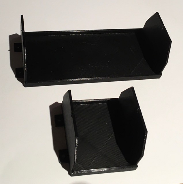
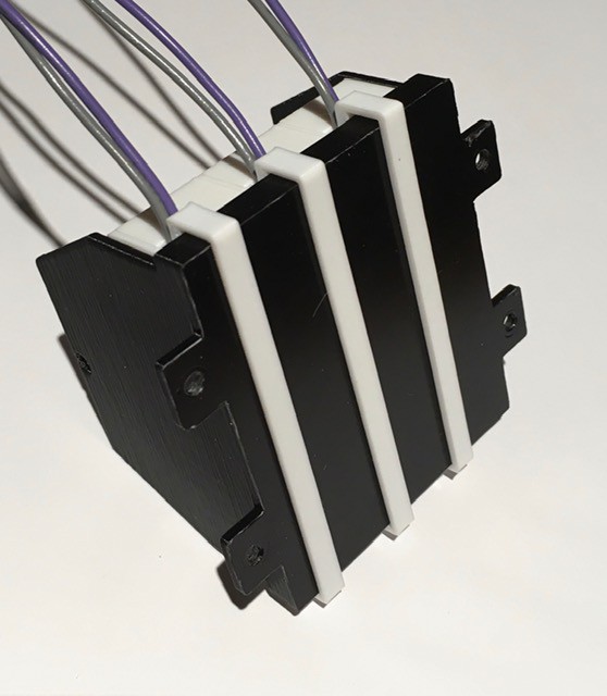
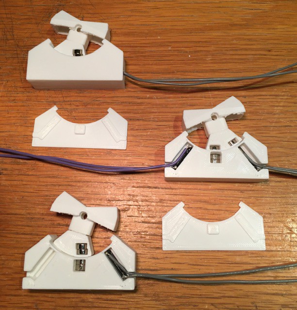
I designed two "cradles" to hold the switch bases.
![]()
The bases slide in snugly.
![]()
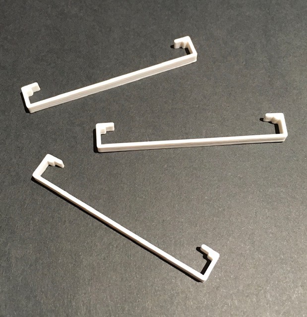
I made some simple clips to hold the base pieces securely in place.
![]()
![]()
Same for the eight switch cradle. I'm running a bit low on filament so mixing colors a bit.
![]()
Next I printed some mounting plates. They have slots for M3 nuts to ensure a strong bond.
![]()
Connected the cradles to the mounting plates with M3 x 10 bolts.
![]()
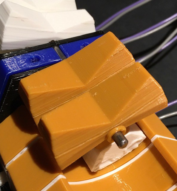
![]()
Cut a 1/8 inch steel rod to span the length of the combined switch assembly and printed some small spacers to help align the switches.
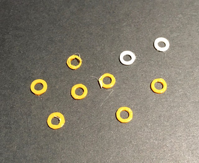
![]()
Starting from one end I began slowly sliding the rod through the pivot holes attaching the rocker switches with their counter weights as I went. Between switches I inserted one of the gaskets.
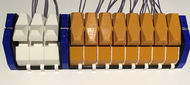
![]()
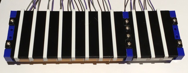
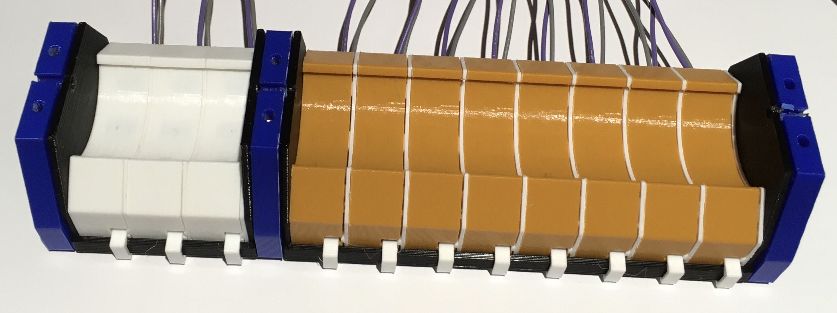
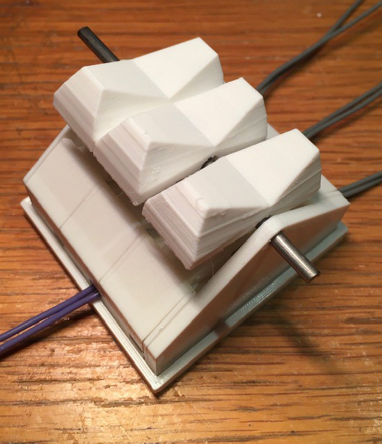
When done the switch assembly should look like this.
![]()
I printed the face plate for the panel (in two pieces, need a larger volume printer). I paused and changed the filament color multiple times to print the text and the logo. All that's left is to attach the switch assembly to the face plate. (Or is it the other way around, the switch assembly is quite massive.)
![]()
That's it. The switch panel is done. It is tweaked a bit from the original. I had to make the characters bigger by about 20% to get them "print" correctly when extruded. The switches when assembled ended up being a little wider than the originals. Since I had already printed the switches, I made the panel holes a little larger to accommodate them. When I get the chance I'll get some black steel bolts so the heads are less noticeable. All-in-all though I'm extremely happy with the result.
-
Banana Plugs
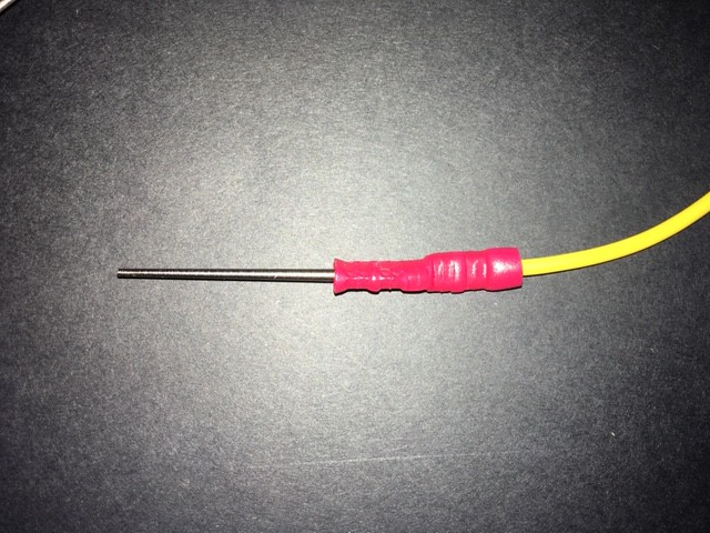
04/18/2020 at 15:31 • 0 commentsI received my 2 mm banana plug samples (not the screw type) and it turns out that they work way better than the taper pins I was considering. Perfect fit for the rivets I will be using. They have a much nicer feel when inserting and they seat better as well.
![]()
They are a little more expensive at about 50 cents per plug verses 30 cents per for the tapers, but well worth it in my books.
-
Final Preparations Before Digging In
04/11/2020 at 17:16 • 1 commentPatch Cables
My taper pin and rivet samples arrived this week.
![]()
So I ran a few test.
The taper pins slide into the rivets easily and hold securely in part because the pins have extremely fine circular ribs along their length. They only go in about 5 mm before stopping though. I would have like for them to sink a little deeper but they work.
I ensured that the panel holes for the pivots were the right size. As it is, it takes a bit of an effort to push the rivet through the hole, but I end up with a secure friction fit that I hope will be enough without having to apply any glue.
I tried soldering a jumper wire to one of the steel taper pins. It turns that it is reasonably easy to make a nice solid connection. On top of that I plan to add some thick shrink tubing for extra support.
The 30 mm taper pins I ordered seemed a little large so I cut one down to 20 mm and it felt better to me. I can order these pins at the 20 mm length.
I did a quick check to see how hard it would be to solder to side of one of the rivets. As expected since they are brass this can be done pretty quickly which is important so as not to heat up the plastic panel too much when making the connection.
So all in all I feel that I have a viable patch cable solution. Before I order the tapers though I am going to try some 2 mm banana plugs that I think might work a bit better. Samples ordered.
Toggle Switches
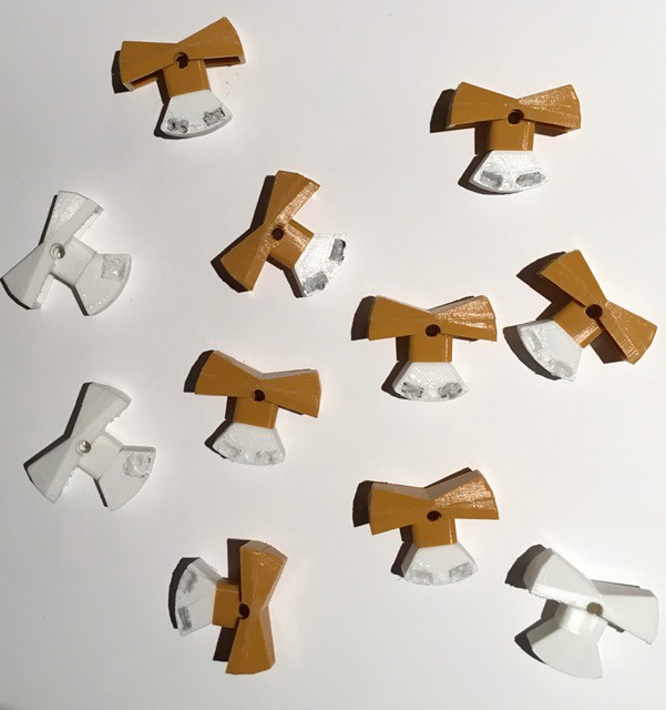
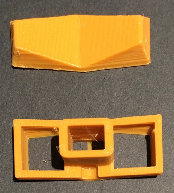
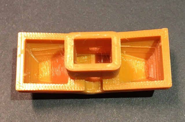
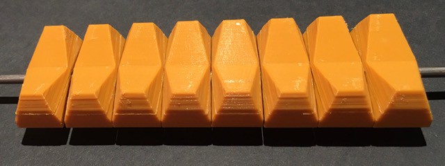
I also received some "light brown" AMZ3D filament that I though might be a good fit for the 8 input switches. Before printing some test switches I split the STL file into two parts to avoid having to use supports.
![]()
I'd rather spend a few seconds gluing then 10 minutes removing support material. You end up with a small seam (where it will never been seen) but with a much cleaner print.
![]()
These pictures appear way too yellow and do not do justice to the actual color which has a nice caramel/butterscotch look to it. It's certainly in the ballpark based on pictures of H-500s that I have seen online.
![]()
Now I don't have an H-500 to compare with, but I have ordered one of Oscarv's awesome PiDP-8/I replicas. I know that he has gone to some lengths to get the toggle switch colors right so I'll have a better example to compare with.
Next Steps
Now that I feel like I have mitigated any risks it's time to move forward. Laying out the front panels and printing them is next on my agenda.
-
A Rivet Alternative
04/06/2020 at 15:53 • 0 commentsAt the same time that I ordered my rivet and taper samples I got a quote on the cost of enough parts for my H-500:
- 350 Flange Head Eyelet - $19.32 (CDN)
- 200 Steel Milled Taper Pin - $59.32 (CDN)
So 80 bucks if I make 100 jumper cables (the number that shipped with the original Computer Lab). But even if I only make say 50 jumper cables that's still $50. So while I was waiting for the samples to arrive, I played around with a rivet alternative idea.
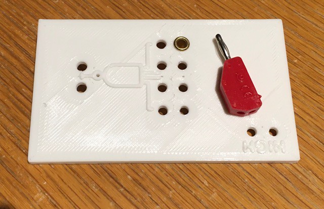
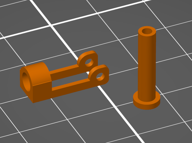
Here is what I came up with:
![]()
![]()
The design uses standard 14 AWG wire for both the jumper cable ends and the connector inside the terminal jack. As the jumper wire is pushed into the jack and comes in contact with the connector wire (which is offset from the center of the hole) the uprights (in blue) will bend slightly allowing the jumper wire to pass and keeping the two wires in firm contact.
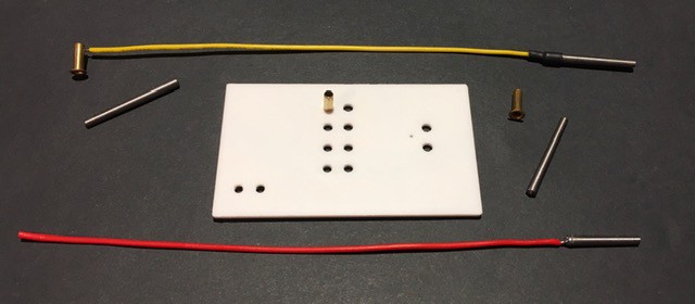
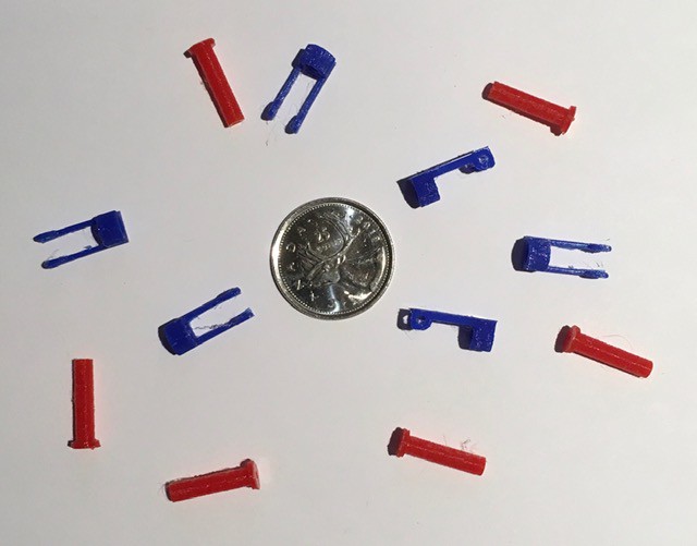
I printed a few.
![]()
It's especially important to print the part that holds the connector wire in this orientation for strength. No supports required, but since the actual parts are so small I did need a small brim.
![]()
They are pretty small. I tried one out.
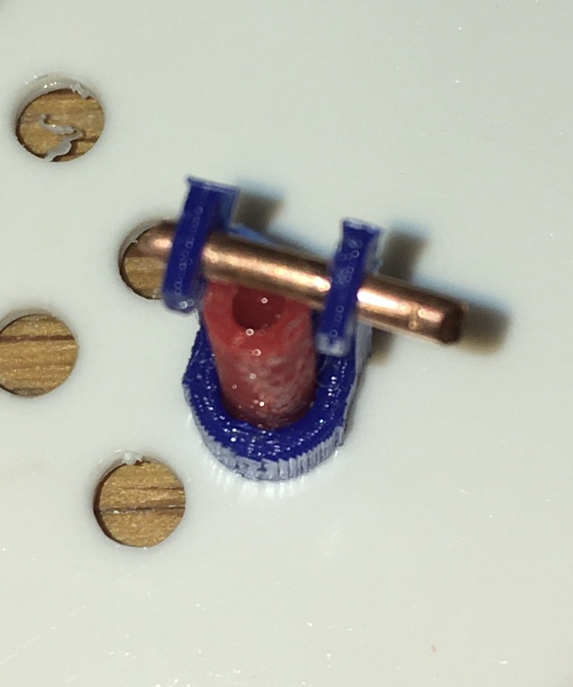
![]()
![]()
And it actually worked pretty well. One of the reasons for this design is that the terminals have to be grouped together pretty tightly in places so I had to check if this would be a problem.
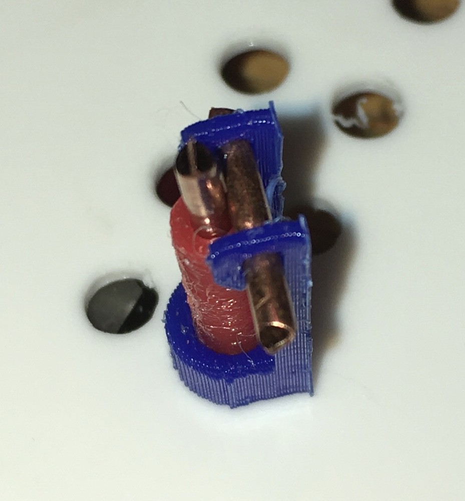
![]()
A little tight but it looks like it will work.
All in all a pretty successful exercise. So will I use this alternative? Probably not, even thought the total cost for these terminals and jumper cables would only be a couple of bucks.
There are a few reasons for this:
- This solution is pretty labor intensive. Because the small parts require brims to print there is a fair amount of post processing to get them ready for use (x 335 remember). In addition the parts will have to be glued in place and again due to the small size will be hard to position. Soldering the connection wires and securing them in place will also be an issue. I'm not afraid of the work, but it feels like I would be asking for trouble in the long run.
- I worry about the long term viability of this solution. As the plastic becomes brittle over time it may not provide the amount of force necessary to maintain good contact between the wires, or may in fact break.
- The plastic "rivets" even if printed with copper colored filament won't look as authentic as the brass equivalents on the original H-500.
Would I ever use this technique? Sure would. In a situation where there were far fewer terminals required, and where the terminals were spaced a little further apart allowing for slightly more robust parts I wouldn't hesitate.
-
Another Riveting Conversation
04/05/2020 at 15:45 • 0 commentsThe main part of this build is going to be the "patch panel".
![]()
On this panel, by my count, there are 335 "terminals" that patch cords can be plugged into. On the original these terminals are small rivets that have been soldered onto a custom rather funky PCB.
![]()
Having decided to forgo a PCB for this version due to cost and accessibility considerations I will have to do something a little different. Fortunately I have some experience in this domain. The Minivac 601 uses a similar patch panel technique. For my Minivac 601 Replica I used 388 rivets and solder lugs to accomplish this:
![]()
![]()
For the Minivac as can be seen on the panel above (one of six) the rivets were set with an anvil holding the solder lugs in place. This worked quite well. For the patch cords I used steel tapers that were sized to "seat" into the rivets forming a solid electrical connection.
![]()
So my strategy for the H-500 is to follow suit with the rivets. I'm hoping though to source rivets with a long enough barrel length that I don't have to set them or use solder lugs, but just solder directly to the side of the barrel that has been pushed through from the front of the panel. This will save a lot of time. Fingers crossed. I have some rivet and corresponding taper samples on order.
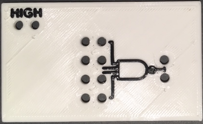
The other part to consider of course is the patch panel itself. As with some of my other projects my plan is to 3D print the panel. This will have to be done in multiple pieces that will fit onto my print bed. I printed a small test patch to validate this decision:
![]()
The sample is scaled to the size of the original. Symbols and text will be "printed" onto the top layer by pausing the print and switching filaments. I think it looks pretty good. Text had to be made a little bit bigger than the original in order to print properly, but the symbol is pretty much to scale.
I did consider one alternative. I could laser cut the panel in one piece, but then I would still have to somehow produce the text and symbols (decals maybe or vinyl) and align them to the panel. At the end of the day, because I want this project to easily reproducible and since more people have access to a 3D printer than a laser cutter, I decided that a one step 3D print solution would be the best fit.
-
Rocker Man
03/11/2020 at 00:31 • 0 commentsBackground
Well rocker switches is actually the reason that I ended up working on this project. At the end of my Mostly 3D Printed Rocker Switch project I posted the following:
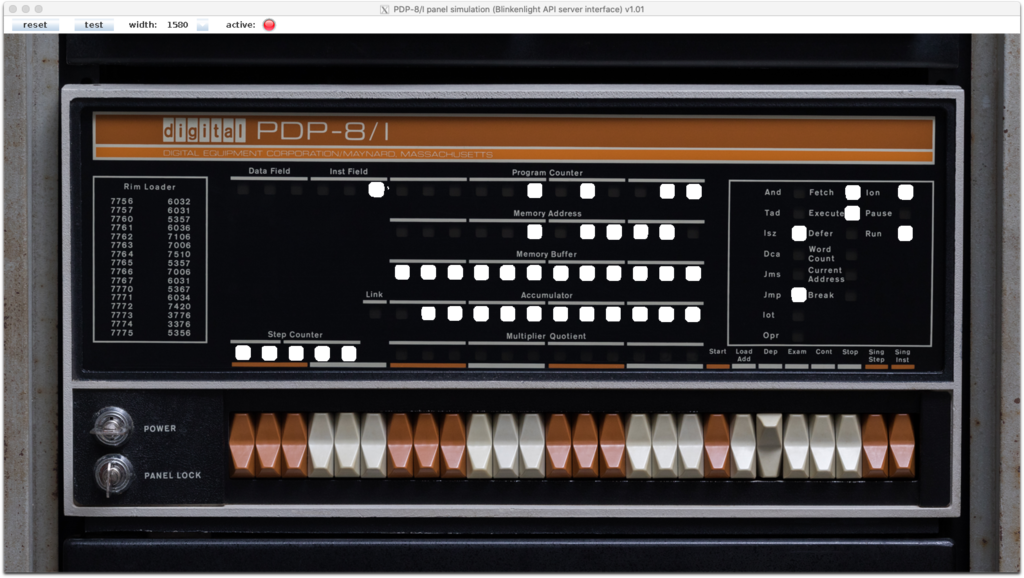
With a workable and customizable rocker switch in my tool kit now, I'm looking at you PDP-8/I ;-)
![]() The remark was made somewhat tongue in cheek, but it did get me thinking about it since I love the look of the switches that they used. I actually started researching the possibility of making an 8/I replica. I soon discovered however that Oscarv had already created an awesome 2:3 replica the PiDP-8/I which I am for sure going to buy when budget permits. So not much incentive to duplicate his great work.
The remark was made somewhat tongue in cheek, but it did get me thinking about it since I love the look of the switches that they used. I actually started researching the possibility of making an 8/I replica. I soon discovered however that Oscarv had already created an awesome 2:3 replica the PiDP-8/I which I am for sure going to buy when budget permits. So not much incentive to duplicate his great work.A short while later I was looking at the System Source Computer Museum Toy Computers page and I saw the DEC Computer Lab. WOW. This was actually a much better fit for both my interests and skill set. I have made replicas of six of the other computer toys on this page five of which I created myself. And the DEC Computer Lab uses the same rocker switches as the PDP 8/I. Perfect.
Making the Switches
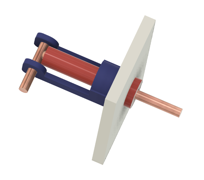
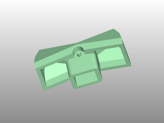
My starting point was an STL version of the PDP 8/I rocker switch that I found at Vince Slyngstad's PDP-8 Stuff page.
![]()
I modified it slightly to have a hole at the pivot point instead of a shaft. Then I modeled a "counter weight" to hold the switch magnets and a corresponding base for the "reciprocating" magnets and the reed switches. You will notice that there are two kinds of counter weights. That's because there are two kinds of rocker switches required, a momentary "spring" return for the three H-500 pulse switches, and an ON-ON variant for the eight input switches.
![]()
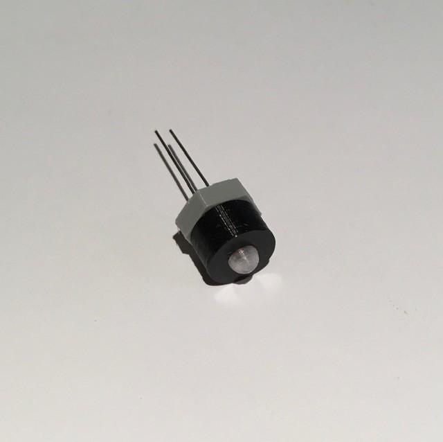
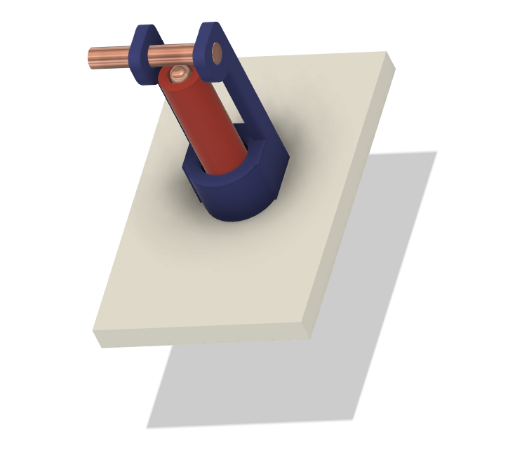
The base has slots and wire guides for each of two magnetic reed switches ( Digi-Key part number 2010-1087-ND). The wires are soldered to the tips of the through hole pins.
![]()
Assembly of each switch is pretty straight forward. Insert the reed switches and magnets (making sure that the magnets in the rocker and the base are oriented to attract) then snap on the base end plate. Note that the momentary contact switches only need one magnetic reed switch.
![]()
I printed a base and added end pieces to accept a 1/8 inch steel rod to hold the individual switches together for testing. I'm still working on how the switches will be mounted to the bottom panel of the H-500.
![]()
Finally here is a video of my switches in action. The end switches are "spring" return and the middle is ON-ON.
-
Design Goals
03/06/2020 at 17:58 • 0 commentsWith this reproduction I hope to provide the best H-500 Computer Lab experience possible. What do I mean by that? Well...
- Visually my reproduction will be clearly recognizable as an H-500. I will strive to provide an outwardly accurate appearance of the original to the best of my ability and within the constraints of the implementing technologies. (Bear in mind that I can't afford one of these so I will be working from images and the kindness of actual owners to provide me with details.)
- Operationally my H-500 will perform like the original. A user will be able to work through the experiments in the Lab Workbook without change or issues.
- I would like for this project to be easy to well, reproduce. To this end I will only be using 3D printed parts and readily available components and materials.
- I will try to keep the total project cost to a minimum.
- A complete set of instructions, parts list, and STL files will be posted to Instructables at the completion of this project so that others could make one should they choose to.
So hopefully my H-500 reproduction will look and work like an original, but I can guarantee (at least for version 1) that the very cool PCB with "surface mounted" components used in the original will not be part of the final design in order to meet cost and reproducibility goals.
![]()
(Maybe version 2?)
-
Motivation
03/06/2020 at 17:10 • 0 commentsSo why would I want to undertake an H-500 Computer Lab reproduction? Well most of the projects that I have been working on lately follow the same pattern:
- They are reproductions of cool computer toys and devices from the 60's.
- Have tremendous educational value (when first released and now IMHO).
- Feature unique and noteworthy designs.
- Due to their age they have become rare and thus expensive and hard to get.
- Perhaps most importantly I think that the devices themselves and their designers deserve to be remembered and honored.
- As a bonus for this particular project, I'm Canadian and the H-500s were manufactured in Canada.
DEC H-500 Computer Lab Reproduction
Reproduce the Digital Computer Lab H-500, a training tool from the late 60's aimed at teaching people the basics of logic circuits.