 Jacques Gagnon
I added PC-FX support with version v0.14! Regular pad and mouse are supported. Any mix of devices is supported for up to 2 players! Refer to wiki for cable schematic and config documentation.
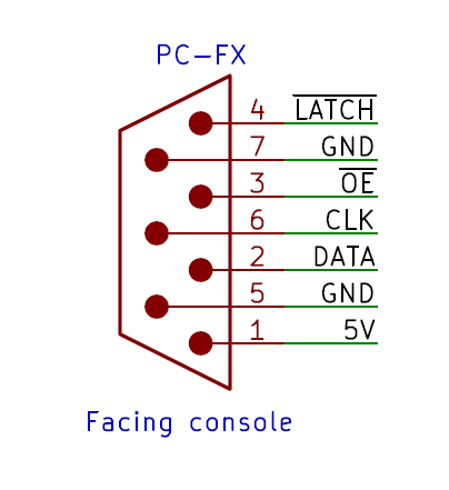
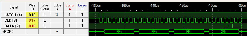
The low level protocol is pretty much like SPI mode 0 for clock and data line. You got the /LATCH line that can be inverted to be use as a CS. An /OE signal can mute the output from the peripheral when high. The console poll the peripherals 5 times in a row every frame. This look like how PC Engine controllers are polled as well for the multitap. Maybe a multitap was plan for the PC-FX as well?
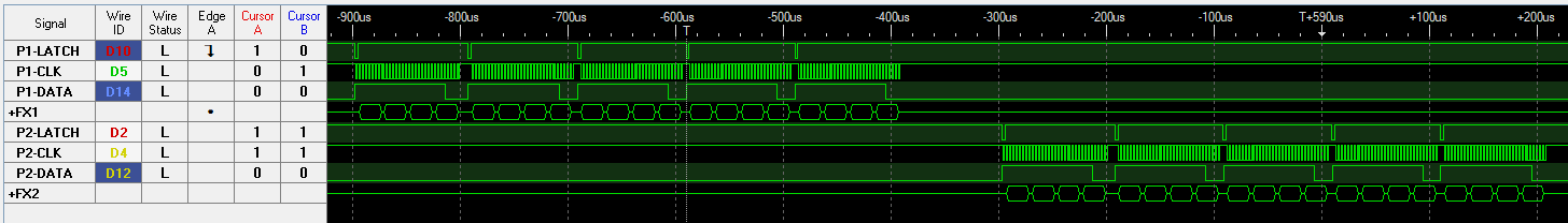
Data line is inverted and LSB is sent first. Clock may sometimes cycle while LATCH is held low, these cycle must be ignored.
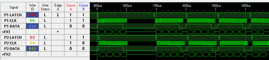
The two controllers are often polled simultaneously.
Getting the ESP32 SPI timing was a bit tricky, In my mind this should be SPI Mode 2 but somehow that was very unreliable. Using Mode 0 timing is rock solid however.
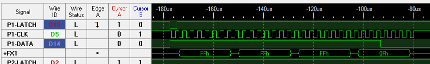
Regular controller
RX: FFFFFF0F (LSB first)
    ││││  ├┘
    ││││  └ ID?
    │││└ Left, Down, Right, Up
    ││└ 1, Mode2, 1, Mode1
    │└ IV, III, II, I
    └ Run, Select, VI, V
Mouse
RX: FFFFFF2F (LSB first)
    ├┘├┘ │├┘
    │ │  │└ ID?
    │ │  └ Buttons (1, 1, Right, Left)
    │ └ X axis (8 bits) (Left: -, Right: +, Two's complement, inverted, LSB first)
    └ Y axis (8 bits) (Up: -, Down: +, Two's complement, inverted, LSB first)
Discussions
Become a Hackaday.io Member
Create an account to leave a comment. Already have an account? Log In.
Just a couple of notes on the PC-FX interface (as I was using this as a reference page for a while)...
1) The 5 reads are intended for reading via a multi-tap; the last scan should be the multi-tap's self-identifier. Since no multitap was ever put on sale, this is not very useful information
2) When a CLK cycle occurs during a LATCH enable, this is intended to reset the multi-tap back to the first controller port.
3) The /OE signal actually determines the direction of DATA - if /OE is low, then DATA flows into the PC-FX; if /OE is high, then DATA flows from the PC-FX to the peripheral. IT IS IMPORTANT TO NOTE that /OE being high should tri-state any external devices trying to drive DATA; otherwise a bus conflict will result and could cause trouble for either the device or the console.
Are you sure? yes | no