Jacques Gagnon
-
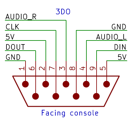
3DO interface
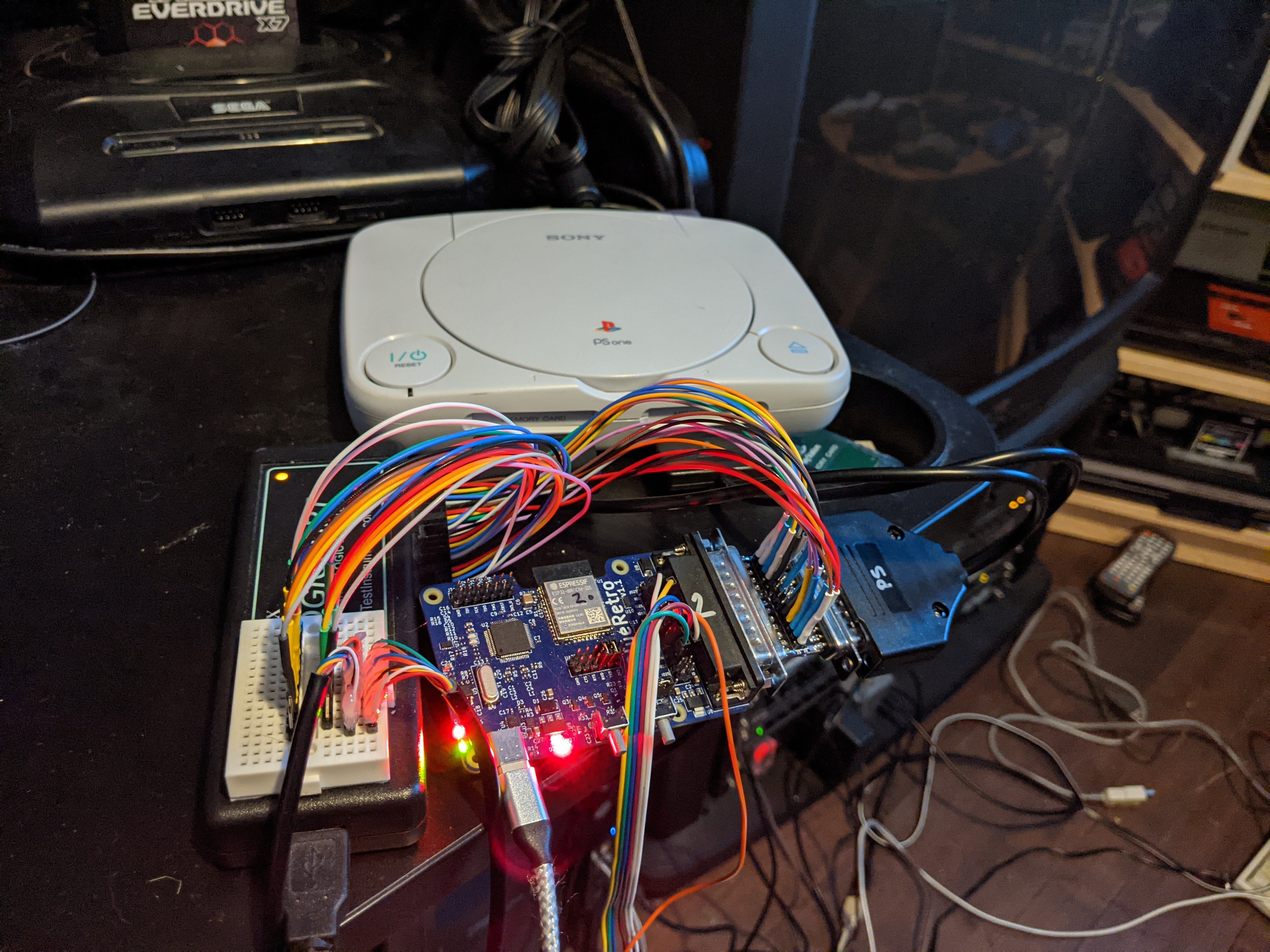
03/29/2021 at 00:45 • 1 commentI just added 3DO support with version v0.13! Regular pad, flightstick and mouse are supported. Any mix of devices is supported for up to 8 players! Refer to wiki for cable schematic and config documentation.
The 3DO interface is quite unique as 8 players are supported via a single port! 3DO peripherals for the most part include an input port on them allowing to daisy-chain controller back to back. No extra port on console or multitap are required!
![]()
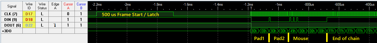
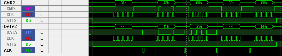
The low level protocol is pretty much like SPI mode 3. You got the CLK, a data output and a data input. Base on my test the console data output is not used by the controller. The big difference with SPI is that there is no chip select signal. Frame start is signaled by holding the CLK line high for 500 us.
![]()
Data from daisy-chained peripherals are simply appended to the transmission back to back, first controller transmitted first. 3DO BIOS and some games will always query for 200 bytes of data. Some games only query what they need. Extra read data is always 0xFF.
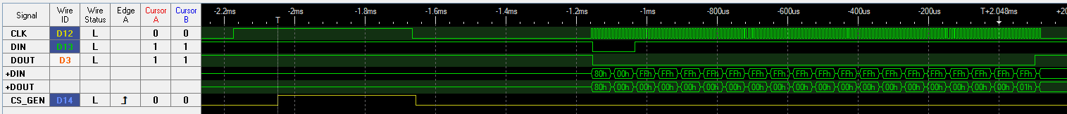
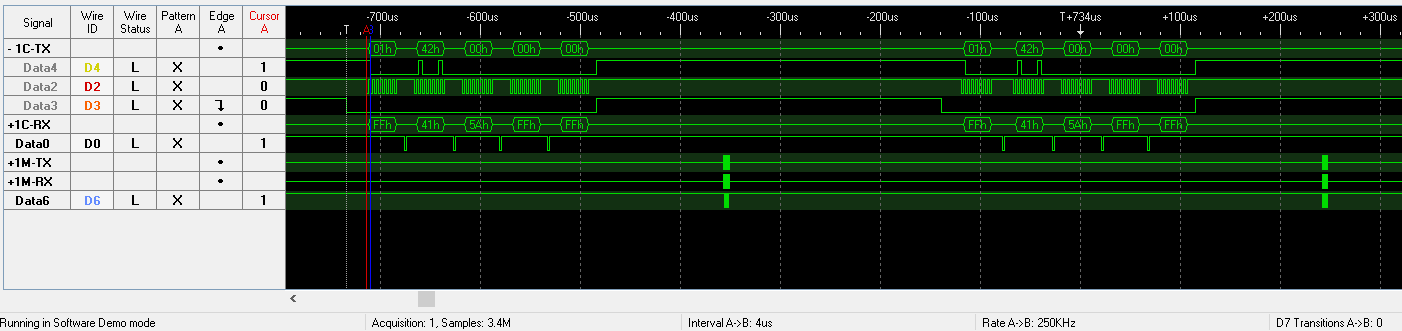
This is one of the easiest systems to implement in BlueRetro. The only challenge was to generate a chip select signal for the ESP32 SPI hardware. The ESP32 SPI slave hardware is unfortunately not very flexible. I loop back my generated CS GPIO output into the ESP32 SPI CS input.
![]()
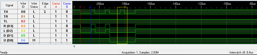
See generated CS signal in yellow base on CLK signal Start Regular controller
RX: 8000
    ││││
    │││└ R, L , 0, 0
    ││└ B, C, P, X
    │└ Up, Right, Left, A
    └ 8, 0, 0, Down
Mouse
        ┌ Y axis (10 bits) (Up: -, Down: +, Two's complement)
       ┌┴┐
RX: 49000000
    ├┘│  └┬┘
    │ │   └ X axis (10 bits) (Left: -, Right: +, Two's complement)
    │ └ Buttons (Left, Middle, Right, 0)
    └ ID
Flightstick
I didn't RE this one my self, base on:
┌ X axis (10 bits) (Left: -, Right: +, Two's complement) ┌┴┐ RX: 017B08802008020000 └┬───┘ └┬┘└┬┘│││ └ IDs? │ │ ││└ P, X, L, R │ │ │└ Up, Down, Right, Left │ │ └ Trigger, A, B, C │ └ Z axis (10 bits) (Two's complement) └ Y axis (10 bits) (Up: -, Down: +, Two's complement) -
2021-03-12 Update
03/12/2021 at 18:08 • 0 commentsQuick updates :)
Just released v0.11.1 to fix a regression from v11 where pull-up on RTC shared pins didn't work anymore. This might give you a lot of problems if you have unused pins left float on your ESP32 module.
Also, v0.12 [edit now out!] will come soon with SNES mouse and Famicom Hori trackball support.
Then finally v1.0 will come probably in early April with N64 memory card support!!
I'm talking about this for months but the HW Beta is really happening soon! I fully expect to be ready shipping around ~20 DevKit boards and cables in early May 2021. I got plenty available for the beta so subscribe here: https://forms.gle/TyieHLHRTFCQXz46A
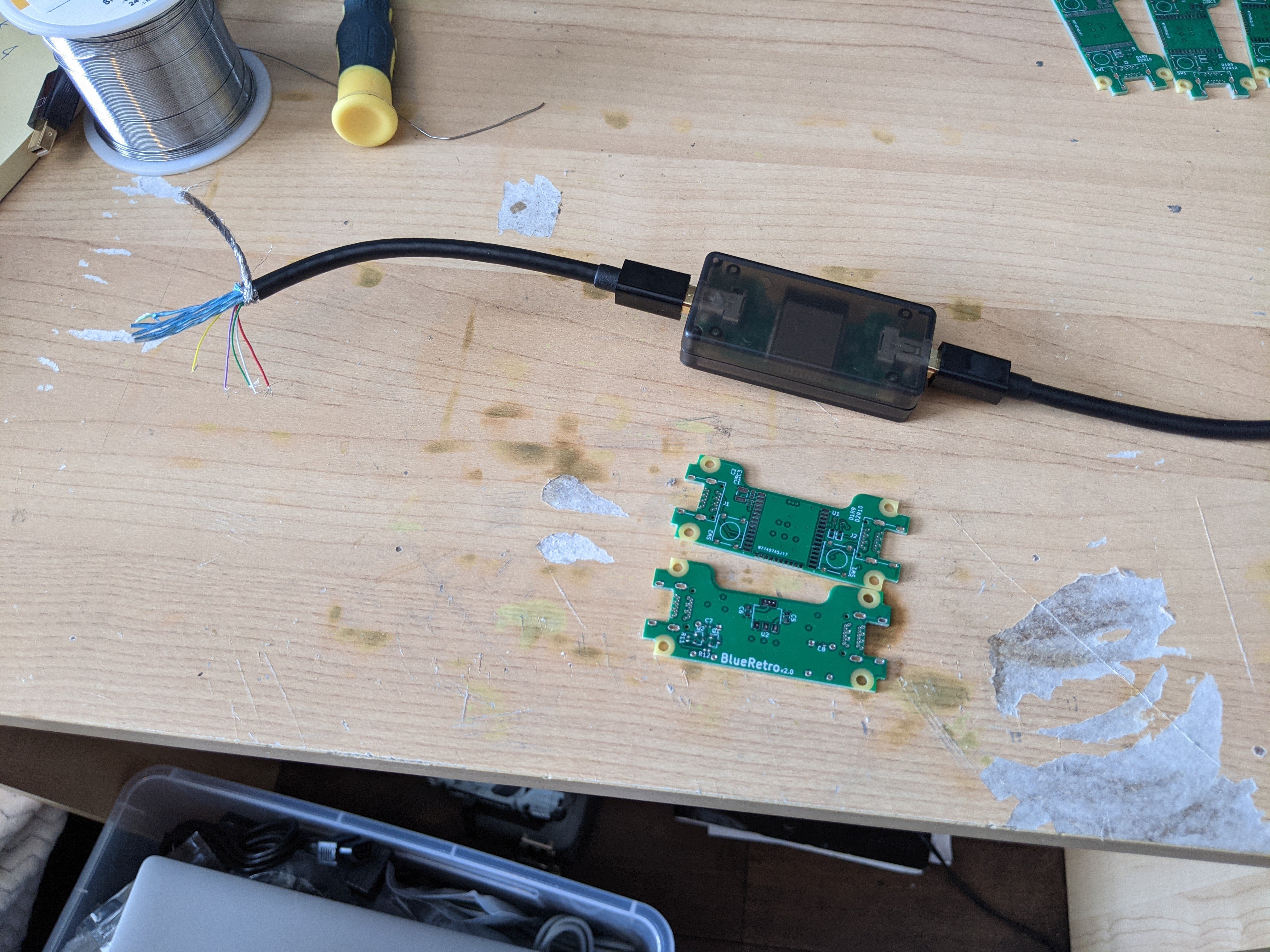
If you rather build your own around an ESP-DevkitC WROOM module check these instructions.I also started to experiment with some concept for BlueRetro v2 (slim version) that I fully intend to launch a crowd funding camping for, probably this fall:
![]()
-
ESP32 RTOS + Bare Metal: Best of Both Worlds?
02/27/2021 at 13:51 • 0 commentsEver since I finished working on the latency tests & improvement, I've been working on trying to free up the 2nd core from its FreeRTOS duty by running it bare metal as originally demonstrated by @Daniel with #Bare metal second core on ESP32. I highly recommend reading the project logs for more detail. I will focus on describing how to refactor a complex application to use this hack in this log.
Goal
My original goal was to free myself from a workaround I have been using since the beginning of the project for bit-banged interface (Dreamcast, NES/SNES and Genesis). The issue with Big-Banging with an ESP32 running meaningful code on both core (this is an important nuance!) like the Bluetooth controller task on Core0 and wired interface on Core1 is that the wired task will get interrupted either by the FreeRTOS tick interrupt on its own core or by some event that requires core cooperation like Flash or DPORT access or something else on the first core. To be honest I haven't made an in-depth analysis of the source of interruption but they are either cause by interrupt on Core1 or some event on Core0.
Original Issue
I can't use easily any of the ESP32 peripheral for NES/SNES and Genesis since the games themselves are bit-banging the protocol. So the way controllers are polled vary greatly from game to game and that would probably make using the I2S peripheral hard. Also the high amount of output lines for Genesis overall and for NES/SNES multitaps make it impossible to use a single SPI slave and we only got 2 on the ESP32. I can see how I could implement Dreamcast's maple protocol using 2 SPI peripheral but again to support 4 players there is not enough SPI hardware available.
Some examples of what happens when we get interrupted while bit-banging:
![]()
Two edges of the Genesis select signal are miss and the output is not updated. ![]()
Two edges of the SNES clock is missed that would result in buttons output being shifted to wrong cycle ![]()
Multiples edges of the Dreamcast input is loss result in corrupted packet receive. If you search a bit online on this subject people will often recommend having a task on Core1 doing a loop without any yield but disabling interrupt on that Core and disabling the Core1 idle task watchdog. This only work if Core0 is not doing anything significant. If you are running the Bluetooth controller task, you will quickly get watchdog timeout on Core0!!
So my original fix was to use the DPORT access locking functions (esp_dport_access_stall_other_cpu_start / end) which does two things. First it disables interrupts on the current core by entering into a critical section and second it generates an interrupt on Core0 than essentially make the Core0 loop doing nothing in a high level interrupt (level 4) until we release the DPORT access lock. The function exists to work around a silicon bug for pre-V3 ESP32 but here I use it only for its locking property we don't really care about DPORT access. But the problem with the DPORT locking is that it is sometimes too long to get the lock. The critical section depends on a mutex and the locking function wait for the Core0 to confirm it's "stall".
While this work around work pretty good for the maple bus, it not 100% perfect for the genesis drivers. I got fewer glitches but I still got some which is unacceptable when playing a game.
My hope was that removing FreeRTOS from the 2nd core would remove the need to stall the first core. It didn't exactly turn that way...
Updating Example to Latest ESP-IDF
The original code from GitHub was base on ESP-IDF v4.0.2. A lot of rework happened since then in the master branch to add support for S2, S3 and C3 chips. Beside the things that moved around one of the problems that prevented it from working is that some initialization code for region protection that used to be in-lined was now a function located on flash. Using the older inline version fixed that issue since anything running on bare metal Core1 can't access the flash as it would corrupt the cache.
Feasibility evaluation
Before going full steam ahead and putting a lot of work porting BlueRetro to work with one core bare metal, I did a few tests on the side to make sure it was worth it.
Did it remove the need for stalling Core0?
My first test was to confirm I didn't need to stall the Core0 anymore. So I used a simple SNES interface task loop with added debug on one of the output data lines. Each time a clock edge is received that code toggle the D1 line. So it's easy to spot when we miss a bit. I did the test and couldn't find or detect any glitch and then I concluded this proved Core0 stalling was not required anymore. So I continued with my next test.
However, I realized this much later but I completely drop the ball when doing this very important test. Running bare metal didn't solve the need to stall the first CPU, it's simply that my test didn't replicate the condition on which the first core impact the second one!
The first problem is that I choose the worst system to test this on, the SNES interface is very resilient to bit skip and they are hard to spot with the logic analyzer or game play. Dreamcast, on the other end, fail right away at the peripheral identifying phase since the packet is so long.
Then using a simple project using two FreeRTOS tasks I reproduced the wrong issue. I had the first core pretty much doing nothing and running my interface on the 2nd task. I saw I was missing bits easily but those were due to interrupt on the 2nd core for the FreeRTOS tick since I forgot to disable them for my test. Then ticking I was reproducing the issue I tried using the bare metal hack and saw no bit miss. This was only because since FreeRTOS was not running on that core there was no interrupt register to it!
Reproducing the first Core0 interference requires meaningful work to be executed like the Bluetooth controller task. If I had only launched it I would have spotted right away, it didn't help. The two months worth of work that followed is a result of this invalid test early on. Spoiler, in the end it's good this test failed cause otherwise I wouldn't have continued working on this!
Can we still run interrupt on Core1?
While some interface requires bit-bang other like N64 (RMT), GameCube (RMT), PlayStation (SPI) and JVS (UART) use the ESP32 peripherals. I still want to run the interrupt handler for those interface on Core1. BlueRetro being a universal adapter with auto-detect at run time it's not possible to compile two versions. So event if running bare metal is mostly of no use for those interface it still got to work.
The main issue here is the way the interrupt handler work by storing a table of the ISR function pointer for each core. The size of this table is determined at compile time and so with the config CONFIG_FREERTOS_UNICORE there is no provision to register anything for Core1.
I initially worked around this by taking over the level 2 interrupt handler as this level is not used by anything in the ESP-IDF. It worked well but I didn't like doing so because it requires hacking into the SDK.
Looking more into the interrupt handler, I noticed a hook that can be enabled to pre-handle the interrupt for testing and that also allows clearing it to prevent the regular handler from running at all! This is documented here in more detail. So by simply adding the -DXT_INTEXC_HOOKS flag I had a reliable way to register interrupt for Core1 without any hacking of the SDK!
Can we avoid making change into the ESP-IDF?
Having the interrupt hook without any SDK change made me want to do the same for the Core1 initialization hook. In the latest SDK the init function start_cpu0_default is a weak symbol so it's actually possible to replace it with our own version! So we can do the bare metal hack with a vanilla SDK!
How annoying is it to run everything from IRAM & ROM?
The big overall rule when running Core1 bare metal is that you can't make any access to the flash anymore. So all function and data need to be in IRAM and DRAM respectively. But it's still possible to run function from the ROM! So function like ets_printf can be run and even a lot of the libc functions are stored there too like memcpy and memset. So really running everything from IRAM/ROM didn't sound like a big deal.
Porting BlueRetro Core1 function to Bare Metal
So thinking all my requirements were met I started porting the whole project wired drivers.
Replacing IDF GPIO & interrupt HAL
I didn't use much of the IDF drivers as they didn't really match my use case. However I used some of the simplest helper function for trivial things like configuring GPIO and interrupt handlers. Those functions are located on flash so I can't really use them anymore. I simply made alternate version of those functions and placed them in IRAM (see gpio.c & intr.c). Most of the underlying functions used by the helper function where low level function that are in-lined. So I could use those directly.
Replacing IDF Ring Buffer
For rumble feedback and keyboard scan code communication between the 2 cores, I was using the ring buffer provided by the SDK. However this module heavily relies on FreeRTOS so I had to replace it. I used liblfds to build a lock-free queue base around two bounded, single producer, single consumer queues. One track the free items while the other track the used ones. I isolated the new queue within its own IDF component to avoid having the lib defines within the main project. The lib didn't support xtensa CPU but I found that MIPS defined value matched those needed by the ESP32.
Do not trust IRAM_ATTR!
I had some crash related to flash cache corruption in my PSX/PS2 driver. However every function had the IRAM_ATTR attribute and all data (including strings and const data) had the DRAM_ATTR attribute set. After investigating for a few days, I notice the problem was going away if I reduced the number of cases in my switch case. None of the individual case was the source of the issue but after a certain threshold of them enabled the issue was showing up! It looks like somehow some of the constants were getting place in the flash regardless of the IRAM_ATTR flag passes some threshold! I resolved this issue by adding a linker fragment file for the project and adding to it all my Core1 source files with the "noflash" attribute. This has the huge advantage to enable using string literal as usual rather than use a variable with DRAM_ATTR.
Turn out we still need to stall Core0!
At that point in the porting process I finally gave the Dreamcast's maple bus interface a try and it didn't work at all! After debugging a bit with the logic analyzer, I immediately saw I was still missing bits! I then realized that my previous testing was invalid by looking back at my test branch.
I walked away from the project for a week, and then decided to try adding the Core0 stall back in the maple driver. I couldn't use the DPORT access function anymore as those rely on FreeRTOS. Base on the DPORT code, I made a simplified version of the stalling mechanism. With this version the locking is only possible one way: Core1 stall Core0. I used high interrupt level 5 as some of the panic code share the DPORT level 4 interrupt. Also the stall start function will not block anymore as no mutex is required and that I moved the validation that Core0 is stall to the stalling end function. This made the maple driver work again. I also gave the genesis driver a try and to my surprise Mortal Kombat 1 6 buttons was now 100% glitch free. Something I was not able to achieve before! Turnout I didn't waste my time!
ets_delay_us do not work anymore!
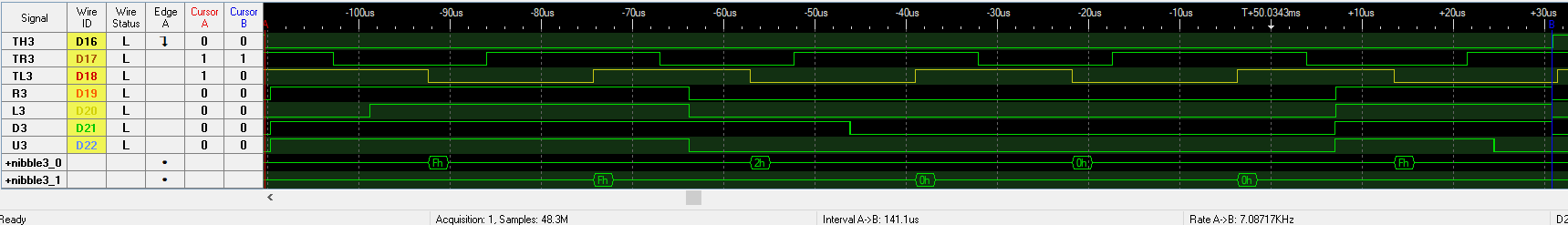
I don't often use the delay function so it took me a while to even notice it was not working. When doing my full regression testing, I notice the SEGA mouse didn't work in Wacky Worlds on the Genesis anymore. This game implement the SEGA Three-Wire handshake very poorly and it requires to emulate the exact timing a real SEGA mouse would take to toggle the ACK line. While debugging with my logic analyzer I saw that the timing was completely off as if the delay was not present.
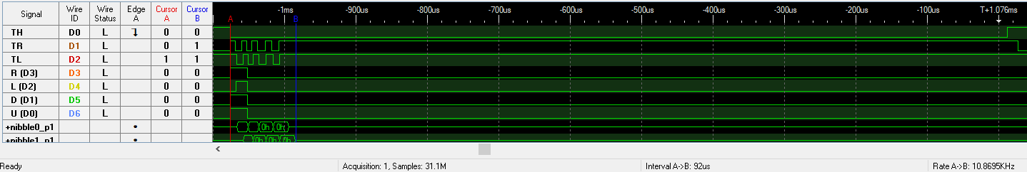
![]()
Without working delay, transmission is done base on the bit request (TR) and ack (TL) flags as fast as possible, notice the game select (TR) is hardcoded to specific length Turn out the ROM function ets_delay_us didn't work anymore! The disassembly of the function is available here and it's actually quite simple. This function depend on the clock rate from xthal_get_ccount function and clock frequency setting locate in the global variable g_ticks_per_us_pro. Base on my test xthal_get_ccount output was fine and even if I could access the content of g_ticks_per_us_pro fine I thought that maybe the ROM code couldn't somehow. So I reimplemented the function by using the CONFIG_ESP32_DEFAULT_CPU_FREQ_MHZ define directly and then my delay went back to normal!
![]()
What Wacky Worlds expect is long delay before ACKs Conclusion
In the end, I think the major improvement came from replacing the DPORT access function by my own core0 stall function that was much faster to initiate the stall. While having the second core free of FreeRTOS certainly help, I bet I could have the same result with it. I did successfully port BlueRetro to use the bare metal hack and everything work well. I kind of like it, so I'll keep it this way. If it turns out to be hard to maintain in the future, it would be very easy to revert anyway. The genesis driver is now finally stable and so I can now move on to implement new features :) .
-
2021-02-27 Update - Release v0.11
02/25/2021 at 12:34 • 0 commentsNew release v0.11 is now available!
The major change in this release is that I reworked the whole adapter so that the second core does not run FreeRTOS anymore. So it's essentially bare metal. That was a lot of work and I will make a separate log about it soon!
The second big change is that I added Kconfig support and in conjunction with the GitHub action CI I can now offer multiple builds! Two types of build are now available: the SD card version as before (now named BlueRetro_universal_sd.bin) and also internal flash (SPIFFS). For each type I also provide the regular universal version with system auto detection. But in addition system hard-coded versions are available. A total of 24 variants are available.
That should be very helpful for people doing DIY version that misses the SD card slot or are hardwired to a specific system. (You don't need to set pin I39 or ground the auto detect pins with the hard-coded build.)
Bugfixes
- Output buffer init overruns
- Fix PS5 Dual Sense L & R trigger indexes
- Remove left over auto parallel init
- Fixup player 2 SEGA mouse init for Genesis
- Update outputs only if a mapping exists
-
2021-01-28 Update
01/28/2021 at 13:11 • 0 commentsAlready a month in the new year!
No new release yet but I figured I'll make a quick update since I feel I still got some weeks of work ahead before anything new.
One of the biggest challenge doing BlueRetro is systems protocols that requires to use software bit-bang. In a chip as complex as the ESP32 running FreeRTOS on two cores you don't control what the CPUs are doing as much as with a PIC or an AVR micro. If you loose the CPU while TX or RX bit bang your data is now corrupted.
So in this context its always better to try to use one of the HW peripheral and abuse them to talk a non-standard protocols. For example the N64 & GC driver use the RMT hardware (for IR remote) to implement Nintendo's 1-wire protocols in a very robust way. But its not always possible to do so, so its important to be able to bit-bang reliably.
I've been experimenting for the better part of the month on trying to restrict FreeRTOS on a single core and run the 2nd one bare metal base on the work of @Daniel with #Bare metal second core on ESP32 . Results are promising so far, I made a small demo here: https://github.com/darthcloud/esp32_baremetal_core1_bitbang_test.
The big challenge in doing so is that the core can't touch the flash anymore and all instructions and data need to be in RAM. I got the PSX driver working which is one of the more complex one with its 3 interrupts. I still got a lot of rework to do to get everything working with that design but it's really worth it as it will end my fight with the GPIOs and make the bit-bang interfaces 100% reliable.
-
2020-12-26 Update - Latency tests & Release v0.10
12/26/2020 at 21:56 • 0 commentsNew release v0.10 is now available!
Wired
- Fixup PSX NHL2000 multitap support
- Add Saturn Keyboard support
- Add PSX Lightspan Keyboard support
- Add SEGA Mouse support for Genesis & Saturn
- Add PSX SCPH-1110 Analog Joystick support
Bluetooth
- Add debug for latency tests
- Reduce latency for WiiU Pro, PS3 & PS4 controllers
Global
- Update to latest ESP-IDF master
Latency tests
I finally got around doing the latency tests. It's a bit of a rabbit hole tbh but I think I managed to keep it simple while getting meaningful numbers. I ditched my original idea of running the test by measuring the delay between button input on the controller and the RGB line black to white transition. It's too much work for nothing. Once the buttons data is within the shared memory the adapter is simply waiting for the console to query for it. At that point any significant delay would make the transmission fail. The fact it work well as show by doing protocol traces tell us their is no significant latency pass that point.
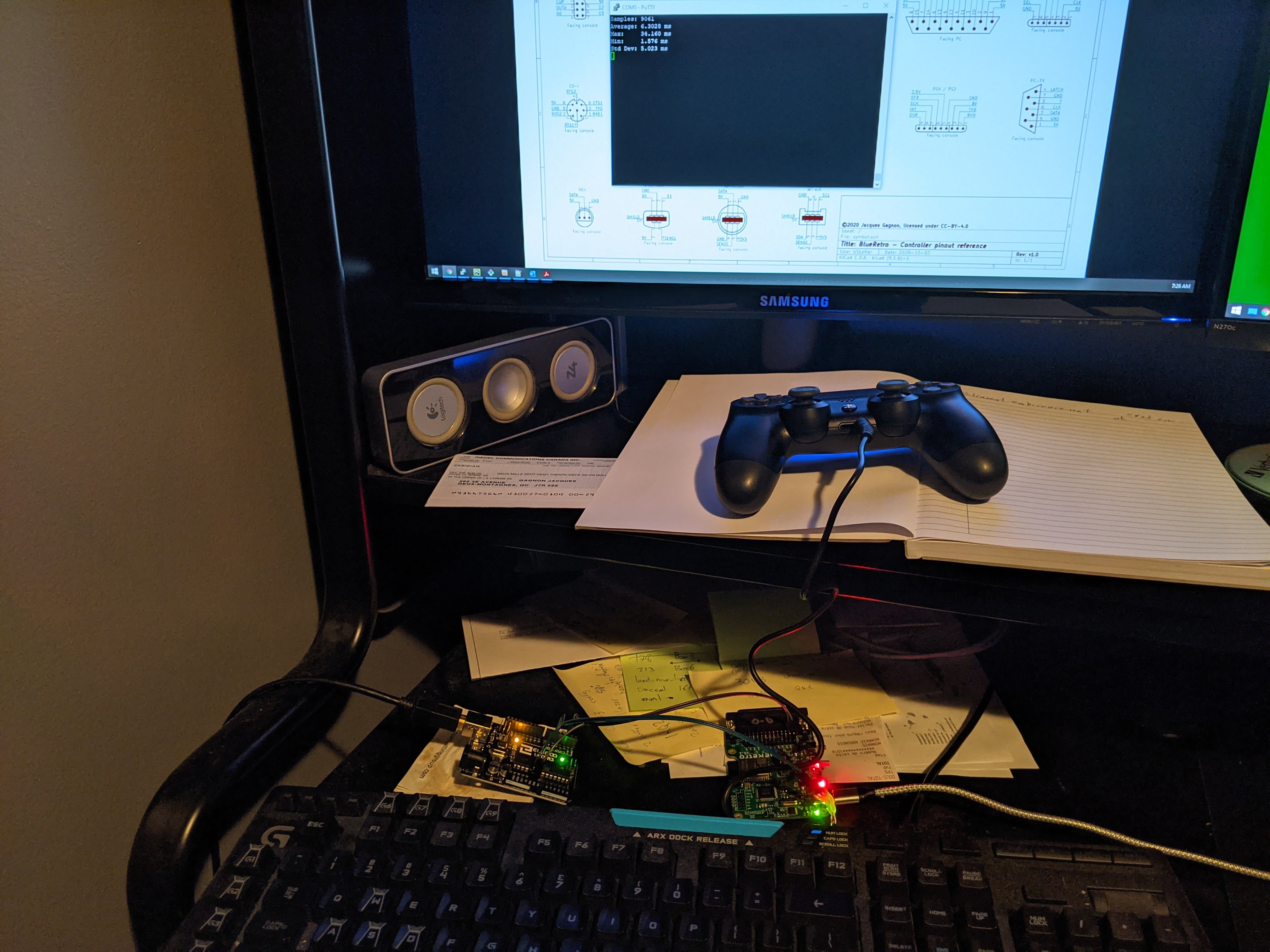
So I settle to simply running the adapter in the 1P parallel mode and hooking up GPIO26 of BlueRetro's ESP32 to an Arduino running a simple sketch using a pin to toggle a controller button and measuring the delay between that and the input pin (Same thing used by MiSTer tests) . I also configured the adapter using a special preset that maps all buttons to the pin GPIO26. I hacked a few controllers to expose one of the buttons on a 3.5mm TRS connector.
![]()
I published the full results here: https://docs.google.com/spreadsheets/d/1god1AdNV7FPIxKj8jwGOPayL9VsWvI7ONhnW3zERaN8/edit?usp=sharing
There are two measurements of interest here. First there is the HID report interval which is very helpful to figure out if the Bluetooth connection is good. It's very easy to get the same numbers from a wireless trace to help compare between various systems. I made a simple python script using Scapy to be able to get the stats.
The second is the latency between the input on the controller and the output from BlueRetro. PS4 & PS5 controllers are the winners using BlueRetro with around ~5.4 ms of latency.
- PS4/PS5: ~5.4 ms
- XB1: ~8.8 ms
- Switch Pro: ~12.4 ms
- PS3: ~12.8
- WiiU Pro: ~13.2 ms
- 8bitdo: ~16.2 ms
- Wiimote: ~16.3 ms
At first I had the PS4 controller configure for 4 ms report interval, while this was good with Linux, it didn't behave as well with the ESP32. Somehow using 0 ms config yield much better consistency in the report interval and obviously better latency. Both PS3 & WiiU controller had very bad consistency in their report interval. Base on this retropie thread I tried to set those controller as master of the connection and this improved the latency a lot! I guess the ESP32 clocking of the baseband don't play too nice with those controllers somehow.
-
2020-12-08 Update - PSX Lightspan Keyboard & Saturn Keyboard support
12/08/2020 at 13:39 • 0 commentsI added support for both the PSX Lightspan Keyboard & Saturn Keyboard in BlueRetro. See pre-release v0.9.1.
N64, DC & GC keyboard only send the raw scan code and let the console software determine the key press and release. Saturn and PSX keyboard are base on PS/2 keyboard protocol running on a different low level interface. PS/2 keyboard send Make and Break scan code to tell explicitly to the console if a key was pressed or released.
More detail here: http://www-ug.eecg.toronto.edu/msl/nios_devices/datasheets/PS2%20Keyboard%20Protocol.htm
This page document well how the Saturn keyboard work:
https://plutiedev.com/saturn-keyboard
The Saturn keyboard mostly use the standard AT Keyboard Scan Codes (Set 2) but some common 2 bytes scan code are reduced to to only 1 byte using non standard code.
The PSX keyboard is only supported by the Lightspan Online Connection CD that was dump only a few year ago. It is not yet known if this use the PS/2 Keyboard/Mouse adapter prototype (SCPH-2000) or if it's a standalone keyboard.
In any case base on some information extracted from the Lightspan software by nocash @PSXDEV forum, the ID & size byte expected is 0x96 which tell use the frame is 12 bytes. I was able to figure out how to emulate basic keyboard functionality. The first byte sent after the 0x5A header is the size of the scan code and the scan code follow in network byte order. I could validate scan code up to 3 bytes. It doesn't look to be possible send multiple scan code at once.
Also the Lightspan softwate probably don't support the longer scan code like Print Screen and Pause. If this is base on the SCPH-2000 adapter the rest of the bytes are probably for the mouse. Scan code reduced to one byte like the Saturn 0x8x ones are also supported as well as the two bytes regular variant.
I didn't observe any data being sent to the keyboard in my traces.
![]()
It would be very easy for someone who own a SCPH-2000 PS/2 adapter to make a dump of the protocol using a special BlueRetro passthrough PSX cable running my SPI Full-Duplex sniffer firmware to make a trace like this one.
-
2020-11-30 Update - Release v0.9 PSX & PS2 support
11/30/2020 at 01:25 • 0 commentsRelease v0.9 finally add support for PSX & PS2 controller emulation!! In addition mouse & keyboard support is added for PSX, N64, GC & DC.
Bluetooth
- PS5 Dual Sense Rumble & LED support
Wired
- PS2 DualShock 2 support
- PSX Multitap support
- PSX Mouse support
- N64 Mouse support
- N64 Randnet Keyboard support
- Dreamcast Mouse support
- Dreamcast Keyboard support
- GameCube ASCII/Sammy Keyboard support
- Disable Auto parallel for now as it interfere with auto detect
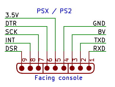
Consult the following documentation for building cables:
Consult the following documentation each system usage & web-config specifics:
-
PlayStation & PlayStation 2 SPI interface
11/27/2020 at 10:13 • 0 commentsI took as base the information provided by Micah's notes on the DualShock 2 controller. My first step before writing the PS driver in BlueRetro was to write a packet sniffer to be able to make easily very long trace compared to what you can buffer in a logic analyzer. This usually helps a lot understanding how each packet relate to each other. See multiple traces here.
Basis
![]() The original PlayStation had a single SPI port share across the 2 controller ports and the 2 memory card slots. Only two Chip Select lines (DTR) were available and so the first controller & first memory card share the first DTR line and the 2nd controller and the 2nd memory card share the second in one. Much like an I2C bus the two devices sharing the same DTR line use an address within the data stream (the first byte) to determine which device is accessed. Controller port devices response to request starting with 0x01 only while memory cards respond to request starting with 0x81.
The original PlayStation had a single SPI port share across the 2 controller ports and the 2 memory card slots. Only two Chip Select lines (DTR) were available and so the first controller & first memory card share the first DTR line and the 2nd controller and the 2nd memory card share the second in one. Much like an I2C bus the two devices sharing the same DTR line use an address within the data stream (the first byte) to determine which device is accessed. Controller port devices response to request starting with 0x01 only while memory cards respond to request starting with 0x81.![]()
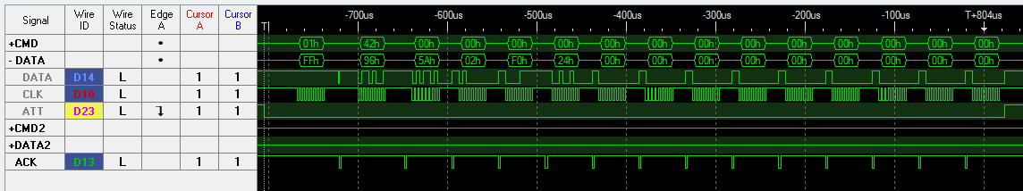
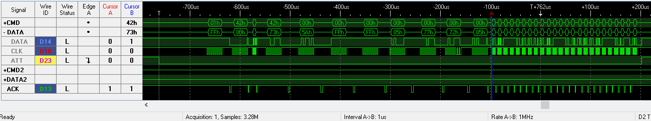
Typical PS controller poll An addition compared to more common SPI interface is the use of the DSR line as an ACK. Every bytes sent by the console needs to be acknowledged by the device for the transmission of the next byte to occur. This line is shared by the four devices just like the SCK, TXD & RXD as well. If a command is not supported by a device, the command byte will not be ACKed.
The two controller outputs (RXD & DSR) are open drain and require a pull-up resistor.
Each transmission is full duplex. Typically clock rate is 250 KHz for controller and memory card but 500 KHz and 1 MHz is used by the multitap. Bits are transmit LSB first. CPOL = 1, CPHA = 1.
    ┌Address
    │ ┌Command
    │ │     ┌Ctrl input (ex: set rumble)
    ├┐├┐  ┌─┴────────┐
TX: 014200000000000000
RX: FF735AFFFF80808080
      ││  └─┬────────┘
      ││    └Ctrl output (ex: get buttons)
      │└Payload length in DWORD.
      └Peripheral ID
Packets always start with a 3 bytes header. First TX bytes is the address to select either the controller (0x01) or memory card (0x81). 2nd TX byte is the command sent by the console. The 2nd RX byte upper nibble is the ID of the peripheral. The lower nibble is the output size in DWORD (uint16_t). The 3rd RX byte is always 0x5A and signals the end of the header. The header is followed by the payload which always match the size reported in the 2nd RX byte even when not all the data is used. Unused TX bytes are set to 0x00 by PSX and 0x5A by PS2.
PS2
![]()
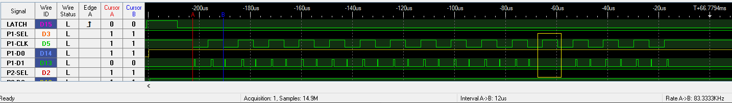
250 KHz DualShock 2 vs 25 MHz Memory card bus The main difference with PSX is that the PS2 has 4 dedicated SPI interfaces for both controllers & memory card. The memory card slot now run at 25MHz while the controller port use same speeds as before.![]()
PS2 Multitap control packet on memory card bus Input devices
Input devices will only answer/ack to frame starting with 0x01.
0x42 Polling cmd
This commands is used by all devices for getting the buttons & joystick status. It is also used to set rumble for Analog & DualShock controllers.
- Digital controller (SCPH-1010)
TX: 0142000000
RX: FF415AFFFF
      ├┘  └┬─┘
      ID   └Buttons(L D R U St R3 L3 Se □ X O △ R1 L1 R2 L2)
On a true original digital controller R3 & L3 are always '1'. Buttons are active low.
- Analog Joystick (SCPH-1110) (In Analog mode) & Dual Analog (SCPH-1180) (In Green LED mode)
TX: 014200000000000000
RX: FF535AFFFF80808080
      ├┘  └┬─┘└──┬───┘
      ID Buttons └Axes(RX RY LX LY)
Exactly the same as Dual Analog & DualShock except the peripheral ID (0x53). They changed the ID only to signal rumble support?? Axis ideal neutral position is 0x80, 0x00 is left & up and 0xFF is right and down.
- Dual Analog & DualShock 1/2 (SCPH-1180, SCPH-1200, SCPH-10010) (In Analog mode)
                  ┌Rumble(Could be map to any byte via CMD 0x4D,
                  │       but typically:
              ┌───┴──┐    1st byte: Right small motor (On-0xFF/Off-0x00)
TX: 014200000000000000    2nd byte: Left big motor (Variable/Off-0x00))
RX: FF735AFFFF80808080
      ├┘  └┬─┘└──┬───┘
      ID Buttons └Axes(RX RY LX LY)
Axis ideal neutral position is 0x80, 0x00 is left & up and 0xFF is right and down.
- DualShock 2 (SCPH-10010) (In Analog mode + pressure activated by game)
TX: 014200000000000000000000000000000000000000
RX: FF795AFFFF957D7388000000000000000000000000
      ├┘  └┬─┘└──┬───┘└┬─────────────────────┘
      ID Buttons └Axes └Buttons Pressure(L D R U □ X O △ R1 L1 R2 L2)
Pressure is maximal at 0xFF. 0x00 unpressed.
Mouse (SCPH-1090)
TX: 01420000000000
RX: 00125AFFFC0000
      ├┘     │└──┤
      ID     │   └Axes(LX LY)
             └Buttons(Left, Right, 0 ,0)
Buttons are active low. Axes are signed Two's complement 8 bits.
Lightspan Keyboard (SCPH-2000 ??? not confirm yet)
(Make scan code)
TX: 014200000000000000000000000000
RX: FF965A016600000000000000000000
      ├┘  ├┘└──────────────────┬─┘
      ID  └Scan code length    └KB Scan code & mouse data???

(Break scan code)
TX: 014200000000000000000000000000
RX: FF965A02F066000000000000000000
      ├┘  ├┘└──────────────────┬─┘
      ID  └Scan code length    └KB Scan code & mouse data???
Scan code are AT Keyboard Scan Codes (Set 2).
0x43 Config mode cmd
Supported by DualShock 1/2 only
Enter or exit configuration mode. This is also used to detect DualShock 1/2 vs legacy controllers (Digital, Flightstick, Dual Analog) as the latter will not ACK the command byte.
TX: 0142000000
RX: FF735AFFFF

          ┌Enter config mode.
          ├┐
TX: 014300010000000000
RX: FF735AFFFF957D7388
      ├┘  └┬─────────┘
      ID   └Ctrl provide poll status via 0x43 if config mode not active.

TX: 0145005A5A5A5A5A5A
RX: FFF35A030201020100
      ├┘
      └ID is 0xF3 until config mode is exit.

          ┌Clear config mode.
          ├┐
TX: 014300005A5A5A5A5A
RX: FFF35A000000000000
      ├┘  └┬─────────┘
      ID   └Ctrl do not provide poll data while in config mode via 0x43.

TX: 0142000000
RX: FF735AFFFF
      ├┘
      └ID revert on config mode exit.
0x44 Enable analog cmd
Supported by DualShock 1/2 only
Require to be in config mode
This allows software to enable/disable the analog mode without requiring users to use analog button.
          ┌Enable analog mode. (0x00 Disable)
          ├┐
TX: 014400010300000000
RX: FFF35A000000000000
0x45 Identity / Status cmd
Supported by DualShock 1/2 only
Require to be in config mode
This command is used to tell between a DS1 and DS2 controller. It also shows the state of the analog mode.
(DualShock 1)
TX: 014500000000000000
RX: FFF35A010200020100
          ├┘  ├┘
          │   └Analog mode state.
          └0x01: ID DualShock 1.

(DualShock 2)
TX: 0145005A5A5A5A5A5A
RX: FFF35A030201020100
          ├┘  ├┘
          │   └Analog mode state.
          └0x03: ID DualShock 2.
0x46, 0x47, 0x4C Get constant cmds
Supported by DualShock 1/2 only
Require to be in config mode
These read some constant on the controller. Response is same for DS1 & DS2.
          ┌Offset 0x00
          ├┐
TX: 014600005A5A5A5A5A
RX: FFF35A00000102000A

          ┌Offset 0x01
          ├┐
TX: 014600015A5A5A5A5A
RX: FFF35A000001010114

          ┌Offset 0x00 (No offset 0x01 for 0x47)
          ├┐
TX: 014700005A5A5A5A5A
RX: FFF35A000002000100

          ┌Offset 0x00
          ├┐
TX: 014C00005A5A5A5A5A
RX: FFF35A000000040000

          ┌Offset 0x01
          ├┐
TX: 014C00015A5A5A5A5A
RX: FFF35A000000070000
0x4D Enable Rumble cmd
Supported by DualShock 1/2 only
Require to be in config mode
This configure which byte offset in the 0x42 poll cmd are used for each rumble motor.
0x00 configure the right small motor, 0x01 configure the left big motor, 0xFF disable this offset.
Typically the 1st byte is the right small motor and the 2nd byte: is the left big motor.
                ┌New rumble mapping
          ┌─────┴────┐
TX: 014D000001FFFFFFFF
RX: FFF35AFFFFFFFFFFFF
          └─────┬────┘
                └Previous rumble mapping
0x4F Polling config cmd
Supported by DualShock 2 only
Require to be in config mode
This enables digital buttons, axes and pressure buttons base on a mask.
            ┌Polling enable mask
          ┌─┴──┐
TX: 014F00FFFF03000000
RX: FFF35A00000000005A
0x40 Pressure config cmd
Supported by DualShock 2 only
Require to be in config mode
This configure in someway the pressure buttons one at a time.
          ┌Button ID
          ├┐
TX: 014000000200000000
RX: FFF35A00000200005A

          ┌Button ID
          ├┐
TX: 014000010200000000
RX: FFF35A00000200005A

          ┌Button ID
          ├┐
TX: 014000020200000000
RX: FFF35A00000200005A
0x41 Polling config status cmd
Supported by DualShock 2 only
Require to be in config mode
This return a mask base on the polling config.
TX: 0141005A5A5A5A5A5A
RX: FFF35AFFFF0300005A
          └─┬──┘
            └Polling enable mask
Multitap
PSX
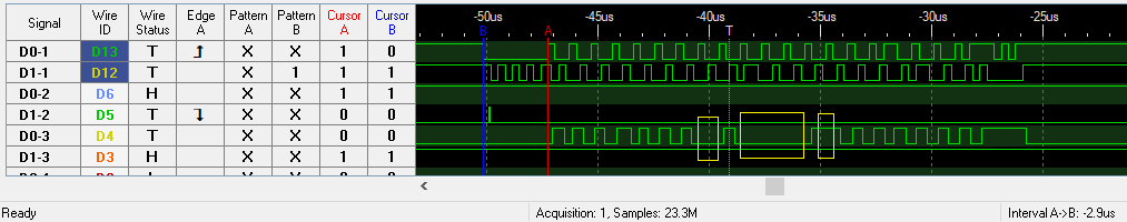
![]()
Typical multitap exchange showing 250KHz bytes mixed with 1MHz ones The PSX multitap aggregate data from 4 input devices and make it available to the system via a single packet. It alsos allow using 4 memory card but I haven't looked at how that part work yet. In any case input devices and memory card part are handled separately. Base on my limited testing with a few games, they look to be happy to see the multitap presence for controllers while only a regular memory card is on the bus.
![]()
Close-up of the packet beginning The multitap is enabled by setting the 3rd TX to 0x01. If this byte is 0x00 then the controller on port A is passthrough to the console as if no multitap was present enabling software without support to be used without removing the multitap. When multitap mode is enabled, a one frame delay is introduced between the console request and the controller response.
┌Enable Multitap │ ┌Port A CMD ┌Port B CMD ┌Port C CMD ┌Port D CMD ├┐├┐ ├┐ ├┐ ├┐ TX0: 0142014200000000000000420000000000000042000000000000004200000000000000 RX0: FF805A415AFFFFFFFFFFFFFFFFFFFFFFFFFFFFFFFFFFFFFFFFFFFFFFFFFFFFFFFFFFFF ┌Disable Multitap ├┐ TX1: 01430001 RX1: FF805A41 ┌Enable Multitap ├┐ TX2: 0142010000 RX2: FF415AFFFF ┌Enable config mode on Port A ├┐ TX3: 0142014300010000000000420000000000000042000000000000004200000000000000 RX3: FF805A415AFFFFFFFFFFFFFFFFFFFFFFFFFFFFFFFFFFFFFFFFFFFFFFFFFFFFFFFFFFFF TX4: 0142014200000000000000420000000000000042000000000000004200000000000000 RX4: FF805A415AFFFFFFFFFFFFFFFFFFFFFFFFFFFFFFFFFFFFFFFFFFFFFFFFFFFFFFFFFFFF └─┬────────┘ └Response from TX3 0x43 from Port A ┌Get identity from Port A ├┐ TX5: 0142014500000000000000420000000000000042000000000000004200000000000000 RX5: FF805AF35AFFFF85756F89FFFFFFFFFFFFFFFFFFFFFFFFFFFFFFFFFFFFFFFFFFFFFFFF ├┘ └─┬────────┘ │ └Response from TX4 0x42 from Port A └ID updated to 0xF3 TX6: 0142014200000000000000420000000000000042000000000000004200000000000000 RX6: FF805AF35A010200020100FFFFFFFFFFFFFFFFFFFFFFFFFFFFFFFFFFFFFFFFFFFFFFFF └─┬────────┘ └Response from TX5 0x45 from Port A![]()
Packet end @ 1MHz PS2
I didn't look much into the PS2 multitap but basically it work by making one of the 4 controller active on the controller port by controlling the multitap via the memory card port.![]()
I think the 3rd TX byte here select which controller to make active on the controller port.
Memory Card
TBD
- Digital controller (SCPH-1010)
-
2020-11-22 Update - Proper PS5 DualSense support
11/22/2020 at 21:59 • 0 commentsSteam beta client recently added support for DualSense controller. Using USBPcap I was able to get a trace to see how it work. The DualSense use report 0x31 for config and buttons reports. Using the native PS5 mode vs the HID mode allow using the LED and Rumble. BlueRetro now support the DualSense rumble. The LED support for Steam didn't work for me so it's still missing on BlueRetro.
See implementation detail here and v0.8.1 pre-release here.
On a different note, PSX & PS2 support is progressing very well. I'm also working on adding keyboard & mouse support for systems already supported.
![]()
BlueRetro
Multiplayer Bluetooth controllers adapter for retro video game consoles