 Patrick
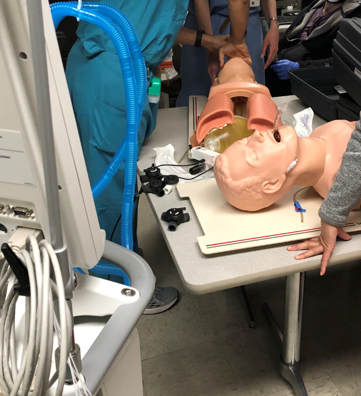
We were able to test the FastTrackTidalVolumeMeter with a ventilator and 2 mannequins.
First, we compared the readings of the ventilator with each meter. The meters ready about 25mL less than the ventilator at 400mL, nobody was concerned with the discrepancy, so we moved on.
Initially, we were deciding on where best the meter should live, at patient vs at the ventilator. And on the ventilator, we tried it on the expiratory flow and the inspiratory flow. We decided that best to have it on the expiratory branch so that if you have a leak, you might identify the leak condition faster. For most of the testing, we left it at the patient. Challenges there:
- long power cable to patient, adds to the system complexity
- ideally you are making flow adjustments while at the ventilator, so you need to be able to see the OLED
- you can set tidal volume by adjusting the ventilator peak pressure, then dial down the individual flow by adjusting the flow control valve
My notes from testing
- A Meter are the patient is not desirable
- meter resting/rubbing on patient's face is not good
- meter power wire (USB) running to meter get tangles, possibly unplugged by patient movement
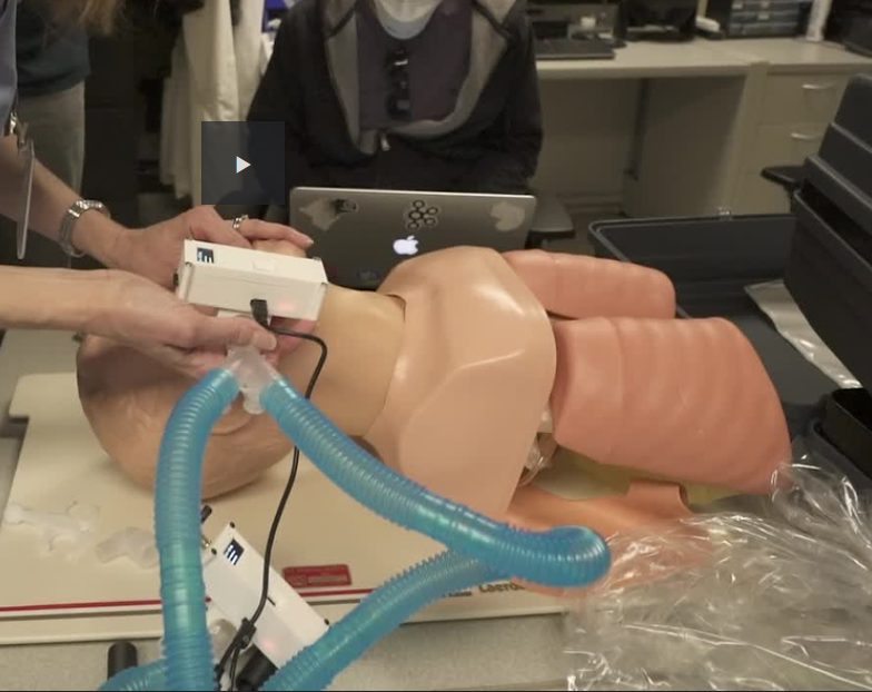
- Meter at the ventilator is desirable. They need to look at tidal flow values as they adjust ventilator controls, standing at the ventilator
- Meter at ventilator will only see flow in 1 direction
- If meter is on the inspiratory flow, it won't see contaminated air
- Doctor preference was meter on the expiratory flow, to determine any upstream leaks
- Doctor wants to see a single device instead of individual units. Can be individual displays for each flow
- Operating the ventilator in volume control mode didn't really work. The control loop got a bit confused with the split breathing circuit
- Operating the ventilator in pressure control mode worked very well. This is recommended by others.
- Ventiltator Peak Inspiratory Pressure (PIP) can be adjusted and control the tidal volume for everyone
- A simple flow restriction adjustment is needed to control the tidal volume on the individual. This can be manual. We tested with 3D printed 3 way valve with some success
- Doctors don't really care about PIP & PEEP, as the readout on the ventilator will apply to everyone
- Unless we give them the ability to adjust PEEP on the individual circuit, then PEEP readout would be needed
- The other individual adjustment they would like to have is FIO2, which is %oxygen to each individual. Not sure how to deliver extra O2, so measuring it is not needed if you can't control it. Likely, everyone would be on same O2 %.
- Humidity, not required, as ventilator will set that and display it for everyone
- Need to pay attention to 22mm male and female connections. Everything I brought had male 22mm (22M) and we needed a handful of female to female couplers (22F-22F). They did not have a supply of these and had to open up "kits" just to get one coupler. This is very wasteful as now the kit is unusable. Once unsealed, it's not able to be re-sterilized and reused. And useless since the coupler was missing.
- FDM 3D printed ISO ports/connectors should be only done vertically. Printing them horizontal will probably leak. The 3 way valve needs to be redesigned so ports are printed vertical.
- The conical 3 way valve leaked and started to vibrate (very noisy) as the flow was restricted down.
- Our mannequins were side by side and we had access above them. Usually, they will be in beds, up against the wall. The ventilator attaches to the wall to get supply of fresh air and O2. ICU room layout will never be as good as we had it. Splitting 2 ways is easy, just put the ventilator between the 2 beds along the wall. Going beyond that will require some thought about breathing tube routing
Discussions
Become a Hackaday.io Member
Create an account to leave a comment. Already have an account? Log In.