 Sam Griffen
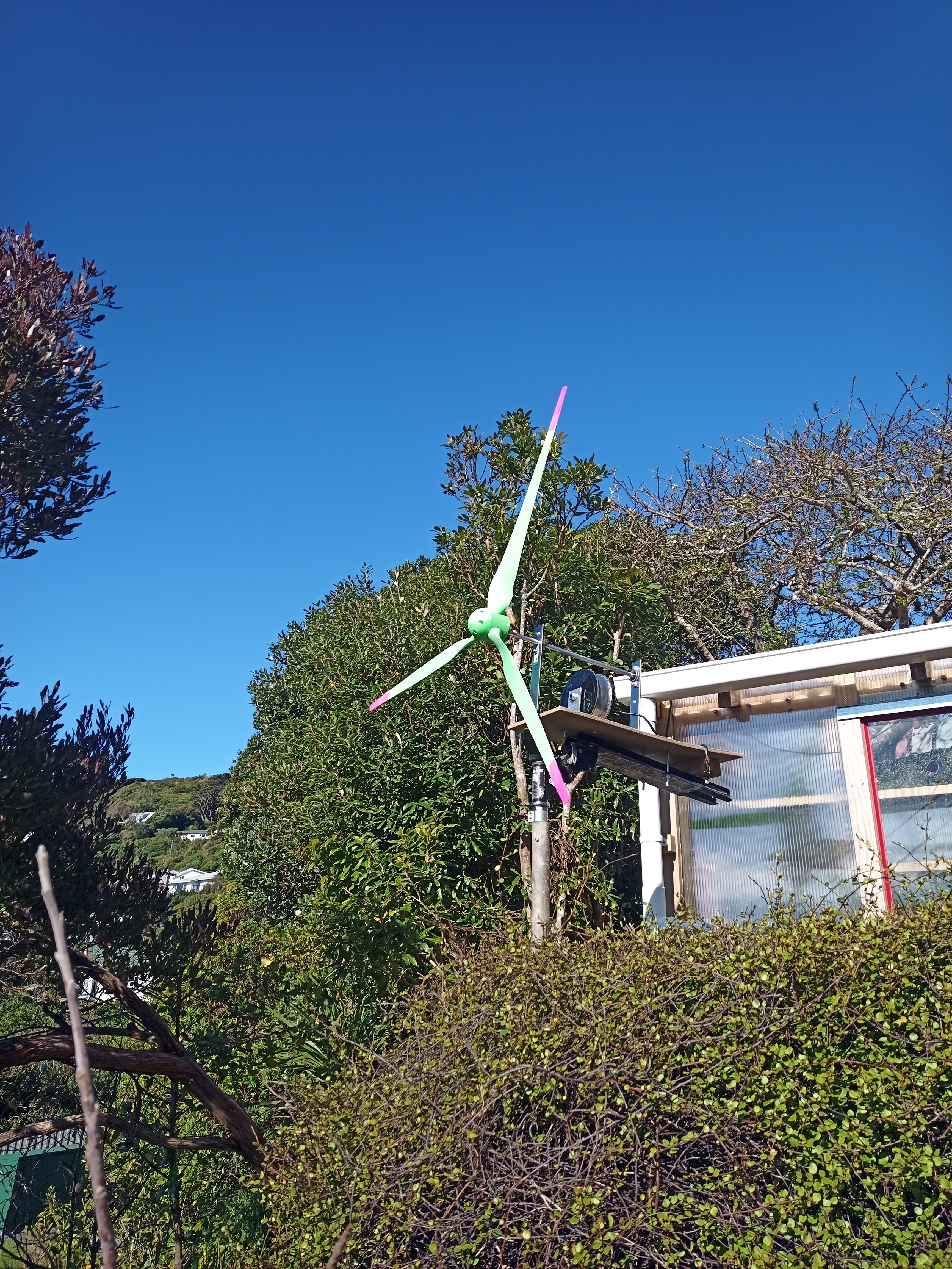
Ultimately, this project will create a system for safely harvesting and utilising wind energy around my own home.
0%
0%
The Scooterbine
Renewable energy from unwanted, unloved motors, and a mean scooter.
Become a Hackaday.io member
Already have an account? Log in.
Just one more thing
To make the experience fit your profile, pick a username and tell us what interests you.
Pick an awesome username
hackaday.io/
Your profile's URL: hackaday.io/username. Max 25 alphanumeric characters.
Pick a few interests
Projects that share your interests
People that share your interests


 Dan
Dan
 Deto
Deto
 Darian Johnson
 David Davenne