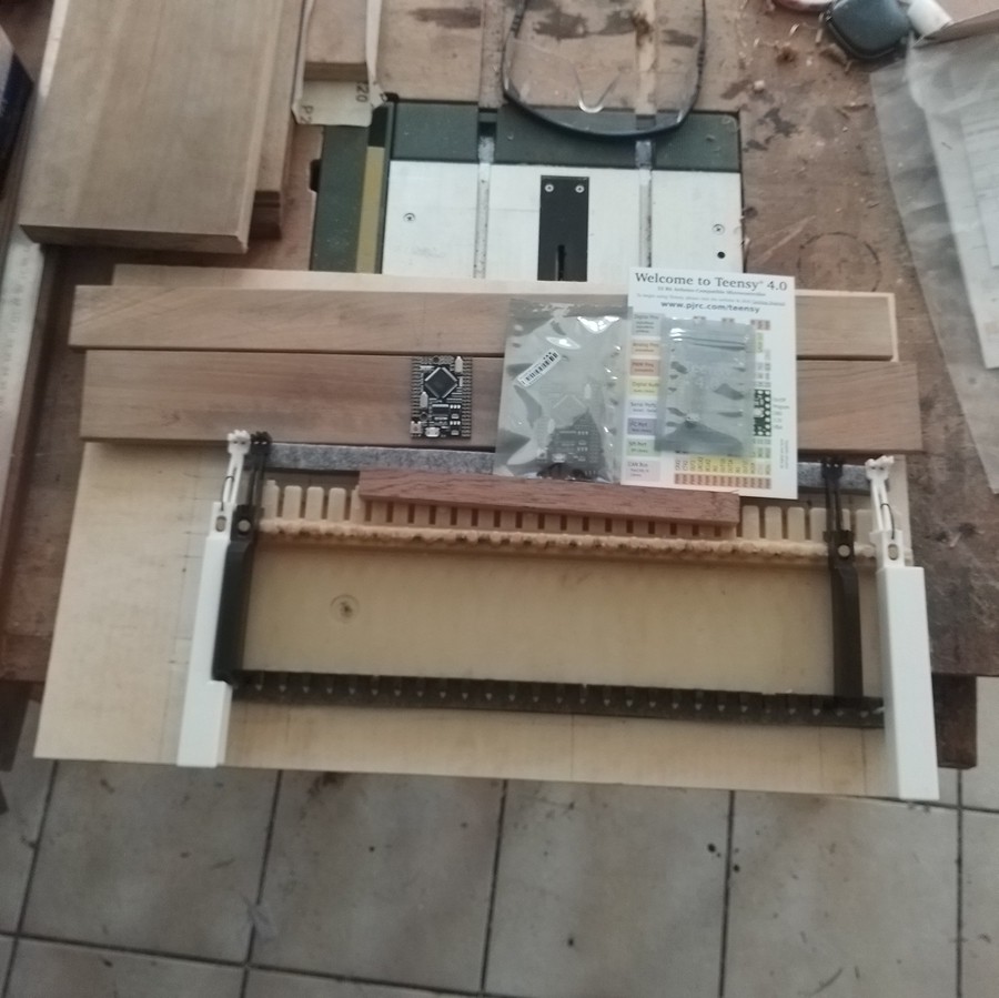
There were Initially no plans made for the body. I simply cut a sheet of 10mm plywood, and placed the keybed on it. Then try to figure out the placement of all components. Taking a measure, cut a part, put it on the synth, and so on.
The wood is wallnut, from an old dining table found on the roadside... For two years I really believed I would repair and use it ! :D
The parts have been cut to length, placed on the plywood bottom, then adjusted following the keybed shape and size.

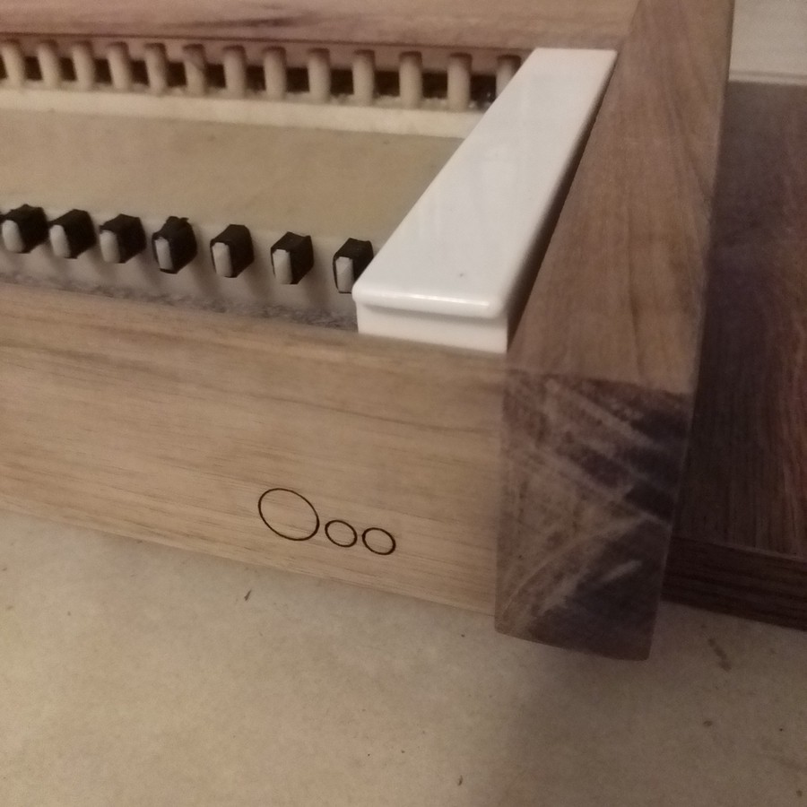
The mark on the front and rear spar is laser-engraved.

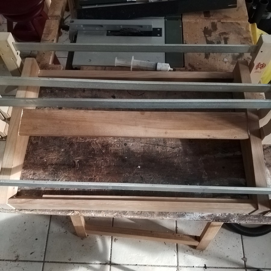
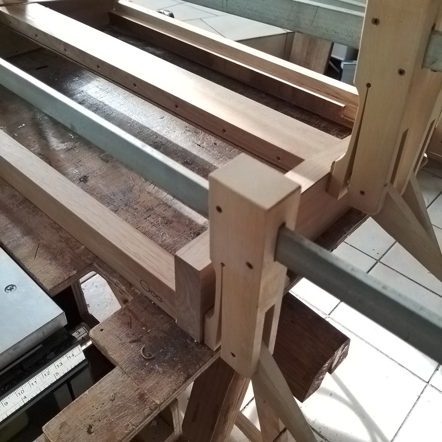
The front and rear spar, and the sides, have a 10x10mm rebate. The bottom panel comes and is screwed into this form. All the parts are glued together with wood white glue ; the front, top and rear spar being held on the sides with a mortise and tenon joint.


Here we see the holes for the screws holing the piano hinge for the front panel.
The wallnut parts have been finished with tung oil. I really love this, but it takes time...
The rear spar was initially straight, but I had to modify it, there was not enough room for any connector between it and the front panel... :/
The front panel is held by two spars. The front one is screwed on the piano hinge. Both have a groove, in which the front panel simply slides. Everything is held in place by the back of the front panel, which is screwed behind on the two spars.
I'm sorry I didn't took that much pictures when doing it, but things will be more obvious if you have a look at the drawings !
A note about these drawings : They represent what I made, but should you do one, you will have to adapt to your keybed. In any case, I was constrained by the pieces of wood I had. The synth sides should have at least 20mm more in height : every mm is counted in the front panel, the pins of the selectors had to be bent so it can be closed. And I don't even know how I will put a support for holding the front panel up. That would make more room for the plugs on the back, too.
It should also have at least 30mm more in length, so the spars are not grooved to let room to the rotary selectors.
Width could be a bit large too, the pitchbend and modulation wheel potentiometers axles had to be shorten to feet between the keybed and left side body !
 Pierre-Loup M.
Discussions
Become a Hackaday.io Member
Create an account to leave a comment. Already have an account? Log In.