Soldering the BGA was amazingly easy. I use some low-temperature solder paste and a boatload of flux with my hot air pencil and everything aligned itself into place. How do I know that I have good contact? Measuring with a multimeter in diode mode, I see a diode drop of ~0.55V between every IO and Vcc. Now I have to solder all the other parts and start talking to the chip. Then comes the hard part, writing good driver software and config code...
The other parts went on just as easy... Well, mostly.
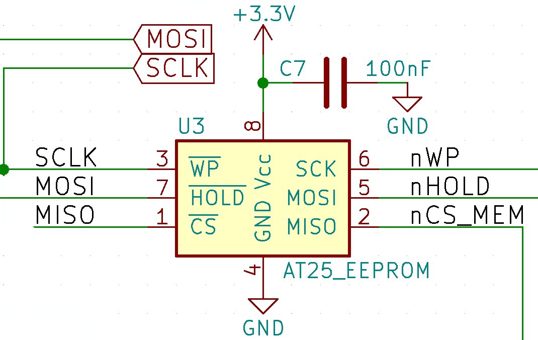
This looks like a nice schematic, all signals are there (sigh):

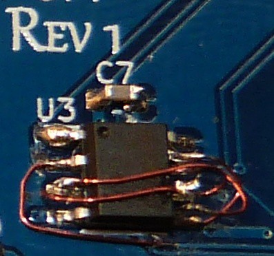
The board needed some wire surgery, but in the end it works and now I have 16Mbit of SPI Flash for character sets and images.

 MagicWolfi
Discussions
Become a Hackaday.io Member
Create an account to leave a comment. Already have an account? Log In.