And it has been terrifying. A whole lot in the physical design has changed, very quickly.
In fact, the overall goal of the project, has changed
We started out using the American version of the design requirements document. which specified a 1.5s breath interval.
That varied greatly from the later released UK ventilator design document. That actually seemed a lot more sane and specifies a 0.3s inhale timing. Switching documents resulted in a five fold increase in our power requirement.
That five fold increase now puts our drive system requirement coming in between 30W and 60W.
Finding a capable motor that can do that for 400k cycles without breaking a sweat increased the weight of the drive section beyond where it was feasible to place this unit on the patient.
Since we are now moving beyond our strict weight limit, I also decided to add a battery backup.
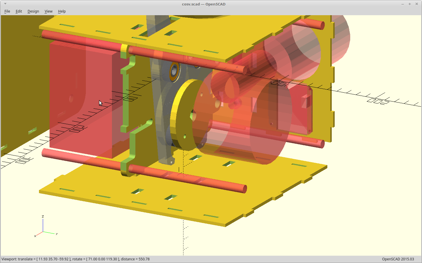
That led to designing a better body to house all of our new toys.
I decided to go all-in on an interlocking pin/slot panel design. The new body and battery meant we now had a transportation ventilator on our hands here, so it got a handle. This meant we needed to move all of our controls and cable connections to where they are less likely to get knocked around when this gets tossed into an ambulance.
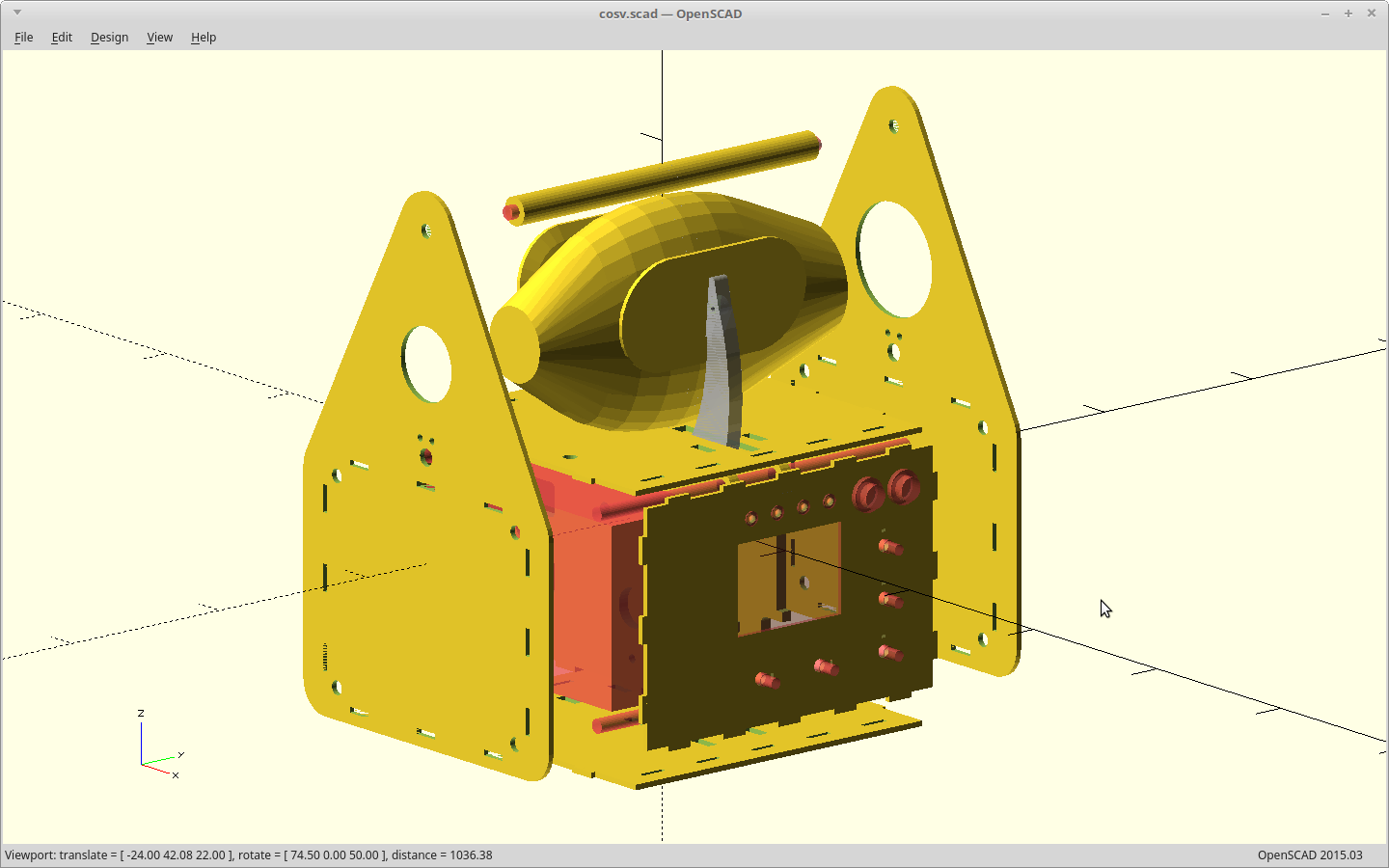
Next step of adding an extension hose to the ventilator bag, and then kinking it off with the pressure release disabled just to see what happened, resulted in us shattering the cam. We have power to spare here.
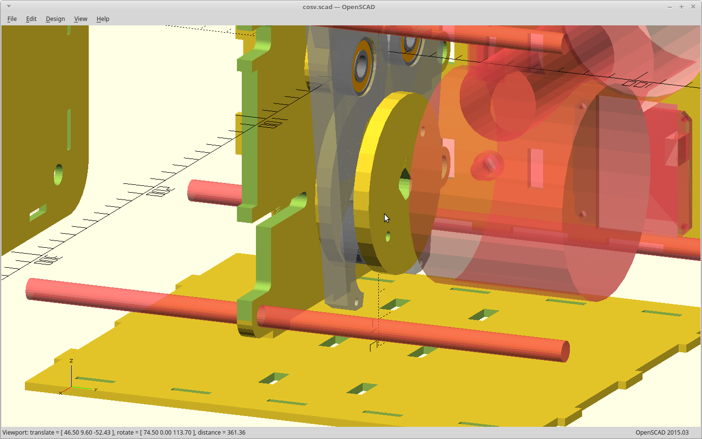
The cam got redesigned as a solid disc, and the cam arms now clear the disc on either side.
If we were to suddenly lose our active feedback for volume/pressure, we decided it would be best to alarm, but still keep doing what we were doing. To do that it is probably necessary to add an encoder to our dumb motor, so we actually know how hard/fast we are pushing. We added an encoder and a spot to put our reader for it.
To keep in simple, our encoder disc is missing one pulse at our two home positions. We can find home by using missing pulse detection and a single photo interrupter. We had a hall sensor before, but it only told us when we were at 'home'. This is much more useful and uses the same number of pins.
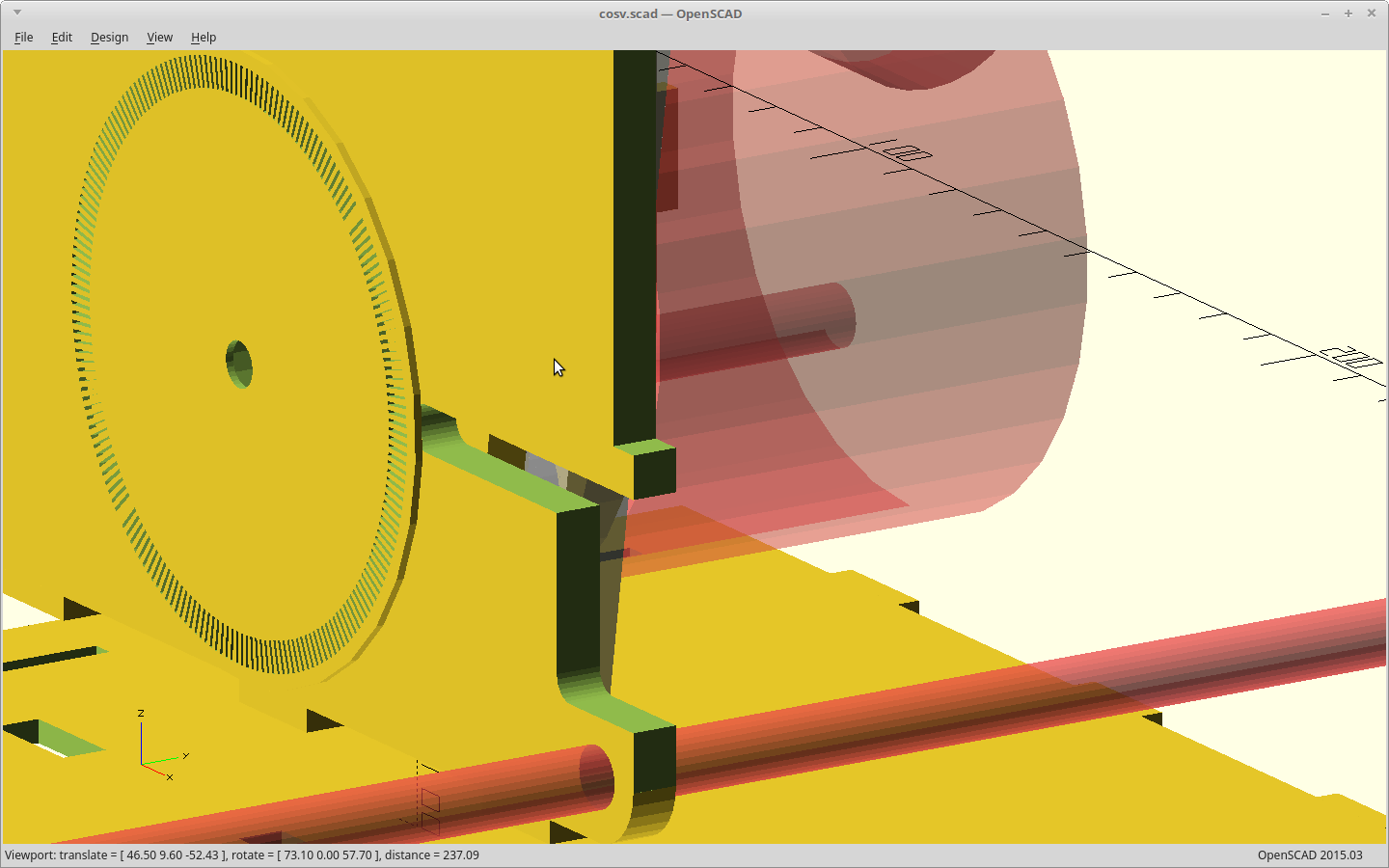
The interrupter slots I picked here are cut at 4x the kerf width of our laser cutter.
That allows for 200 slots and still having more blocked space than cut.
Two hundred probably sounds really familiar, and it should. That is also the step count for the vast majority of NEMA 34/NEMA 23 stepper motors. I think you see where this is going....
As for the kerf to do this, don't get nervous here. Totally dialed in, the best our laser can do right now is 0.15mm. That's about 50% over spec. You'll be fine.
The complexity of all these new parts led me to model the outline of every single part. The clearance to some of them is really close, and I have been bitten here.
For example... the first version of this just eyeballing the motor position ended up with the threaded rod the stack was built from going ever so slightly through where the motor case was. Yep.
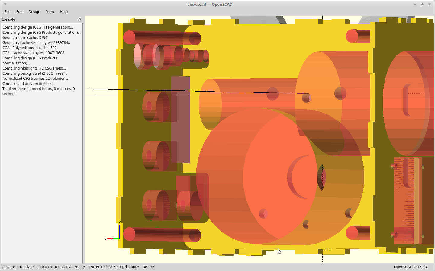
The files are cutting now.
Tomorrow is going to be very exciting.. :)
 MasterOfNull
Discussions
Become a Hackaday.io Member
Create an account to leave a comment. Already have an account? Log In.