You can use these boards as a good-ish cheap logic analyser.... but it'd be nicer if they had some buffering on the input pins......
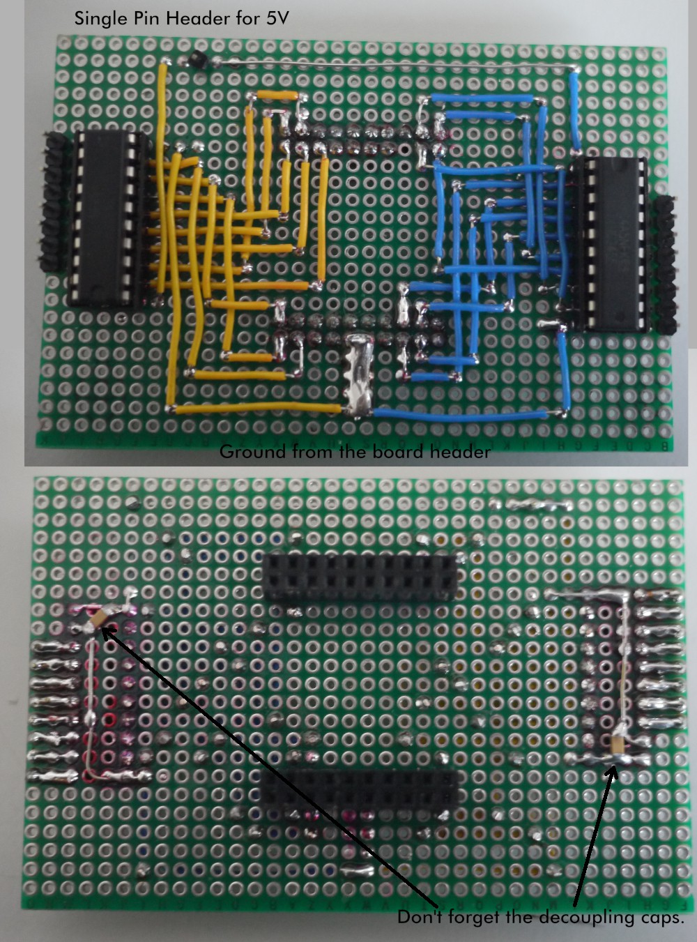
Adding Buffering to LCSoft CY7C68013A Mini Board
To make the experience fit your profile, pick a username and tell us what interests you.
We found and based on your interests.
You can use these boards as a good-ish cheap logic analyser.... but it'd be nicer if they had some buffering on the input pins......
The 74HC245 chips need a 5V power supply which isn't available on the board headers but is available on the USB.
I "steal" this from the board by removing it's power switch and connecting a flying lead to it's 5V lines.
But you have to make sure you short out the 5V and GND lines of the switch or the board won't come on any more.
It took me a while to come up with a board layout so that you can get at the buffered inputs, and the chips don't obstruct the USB socket or the jumper that's on the board. I don't normally use this double sided matrix board stuff but it seemed the only way for this project. I've used some really thin wire and a lot of connections are with 2 wires in one hole. That's a bit unorthodox, but I'm not familiar or confident with the deliberate solder-bridge method of construction these boards prefer.
The main thing to watch for here is chips and input headers on the top and the board headers on the bottom.
The 74HC245 has a nice easy chip layout and Sigrok have a nice map of what header pins to use: https://sigrok.org/wiki/Lcsoft_Mini_Board so I leave it up to you to work out the exact wiring details.
The it's just a matter of pushing the headers together and attaching the 5V lead.
Create an account to leave a comment. Already have an account? Log In.
Become a member to follow this project and never miss any updates