With the current global crisis this project is designed and should work but is untested as I am unable to spare the funds to buy the parts. However I wanted to release this out there anyway should anyone wish to use it or help finish the design!
Make your own infra-red remote control
To make the experience fit your profile, pick a username and tell us what interests you.
We found and based on your interests.
With the current global crisis this project is designed and should work but is untested as I am unable to spare the funds to buy the parts. However I wanted to release this out there anyway should anyone wish to use it or help finish the design!
UniversalRemote.inoNeeds following Libraries: PinChangeInterrupt and IRremoteino - 4.05 kB - 04/30/2020 at 11:23 |
|
|
Universal 19 button remote.skpSSEYO Koan Play File - 2.55 MB - 04/29/2020 at 15:13 |
|
|
Universal Remote.kicad_pcbkicad_pcb - 298.99 kB - 04/29/2020 at 15:12 |
|
|
Universal Remote.schsch - 16.14 kB - 04/29/2020 at 15:12 |
|
|
Universal Remote.propro - 688.00 bytes - 04/29/2020 at 15:12 |
|
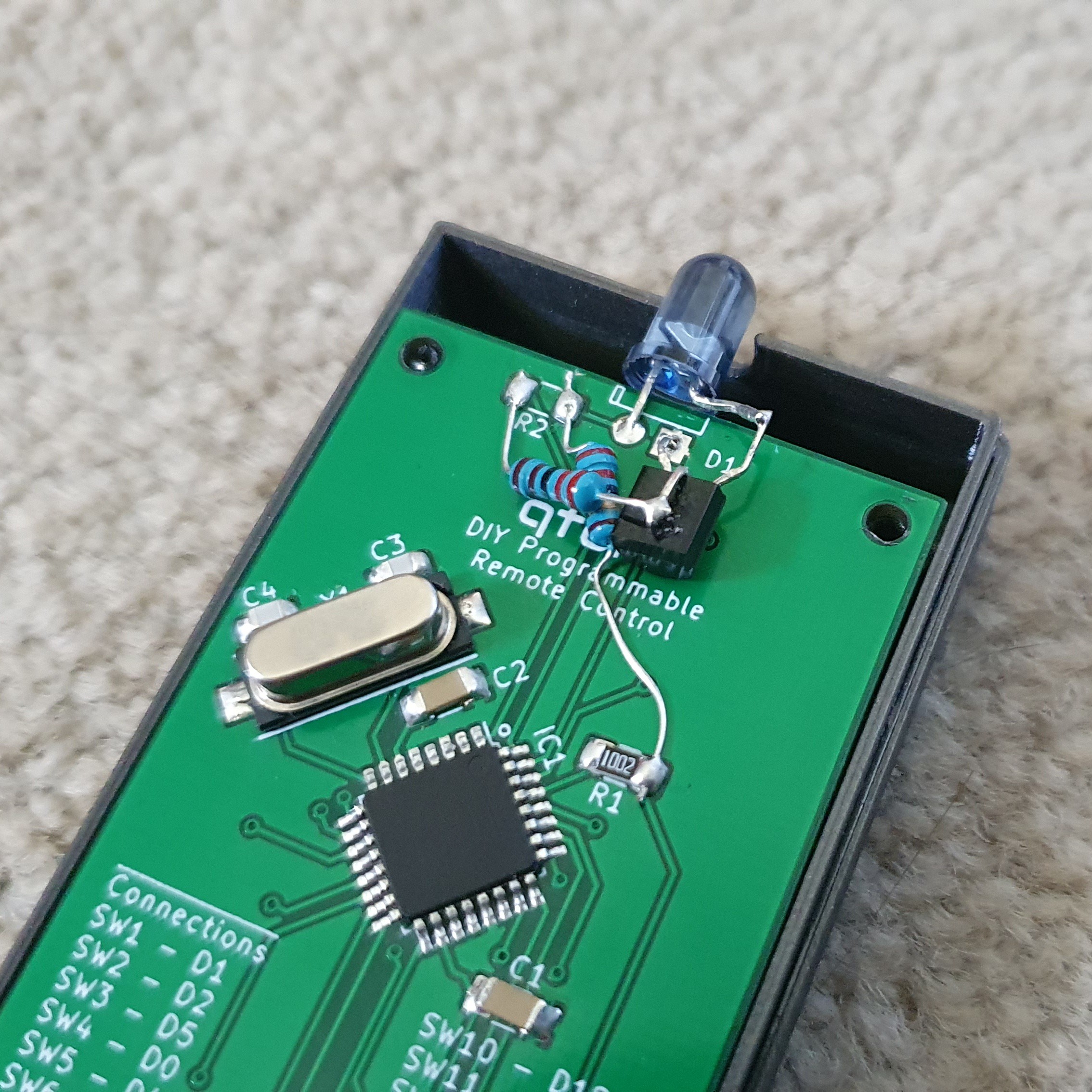
The current design has the IR LED connected directly to the ATMEGA via a resistor which sets the current in the LED to about 40mA(ish). That's the maximum amount the ATMEGA can provide per digital port. This does allow it to work reasonably well but the range is a little low. With the ATMEGA working at 4MHz it should work down to about 1.8V, meaning at that voltage the LED would be running at about 17mA making the range worse. The LED I am using has a continuous running current of 50mA and a pulse at 1A. Either way well above what the ATMEGA can provide. I have modified the circuit to use a transistor to bump the current up in the LED to 85mA when at 3.3V (limiting resistor of 27R) and at 1.8V the LED will still be running at 30mA.
I used a BC548 (what I had available), connecting the base to the ATMEGA via a 2.2K resistor and the LED via a 27R resistor (although I only had a 22R to hand so it is running the LED at 100mA+). I'll be updating the circuit and PCB to use this arrangement in the coming days.
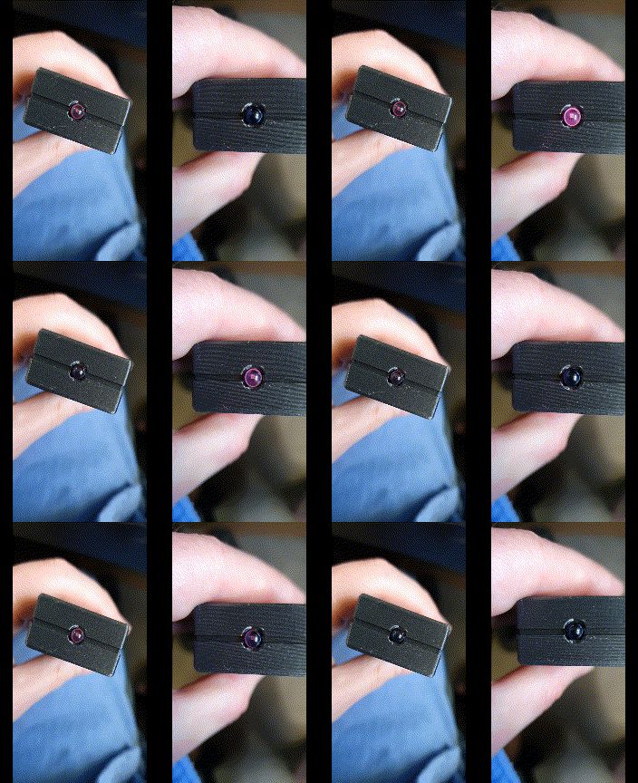
Difference between without transistor (left side) and with:
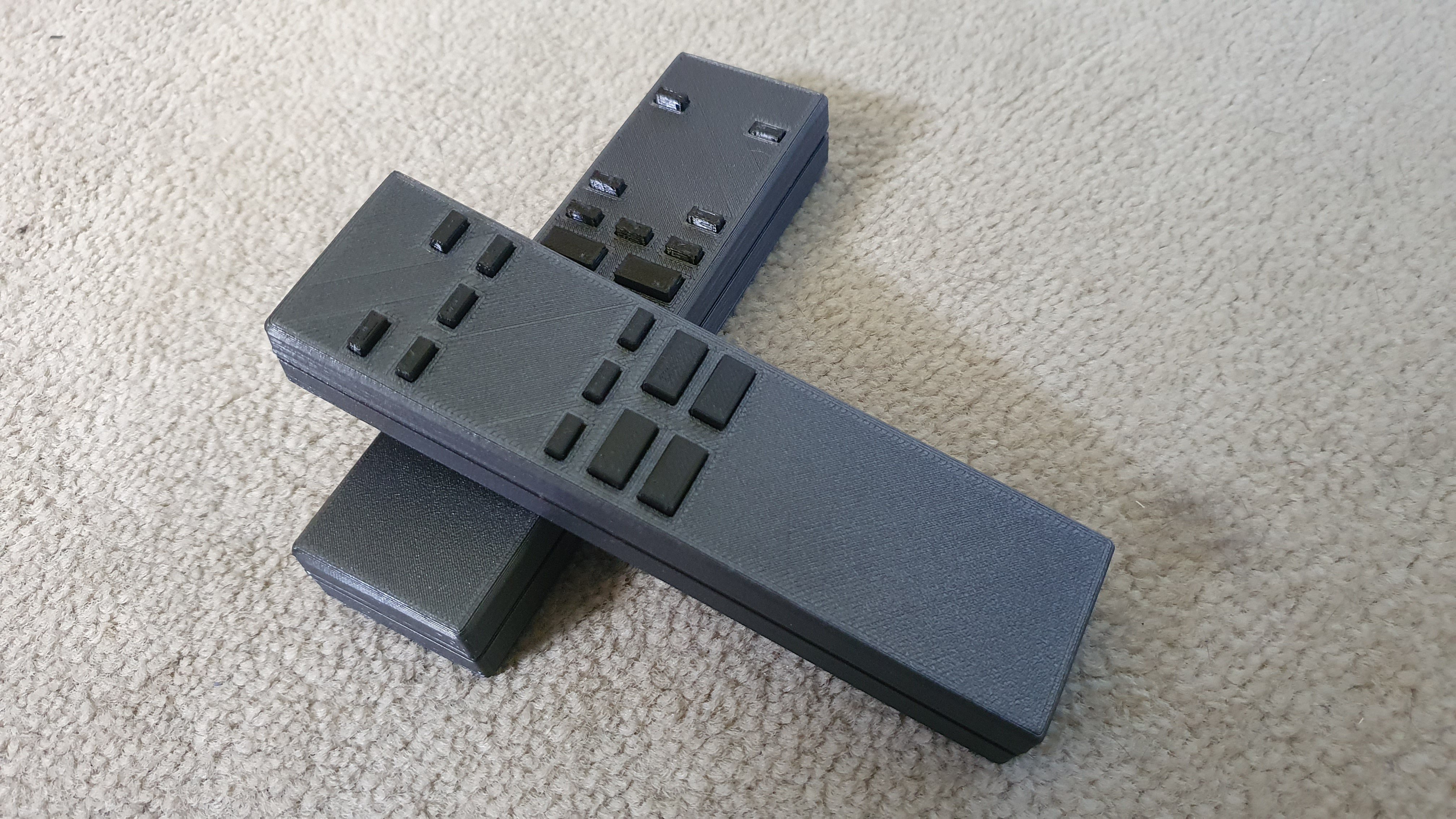
On another note, I have now made a second remote control for my cassette player which is working well to! Just need to get the stickers printed and attached!
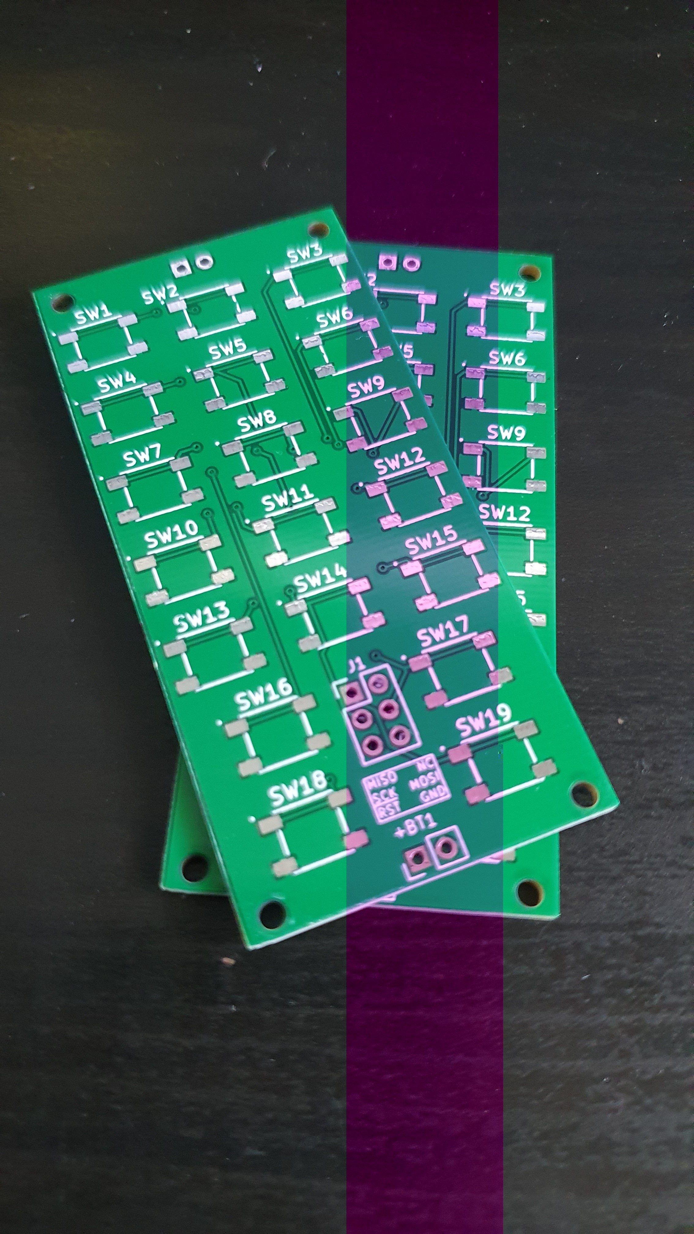
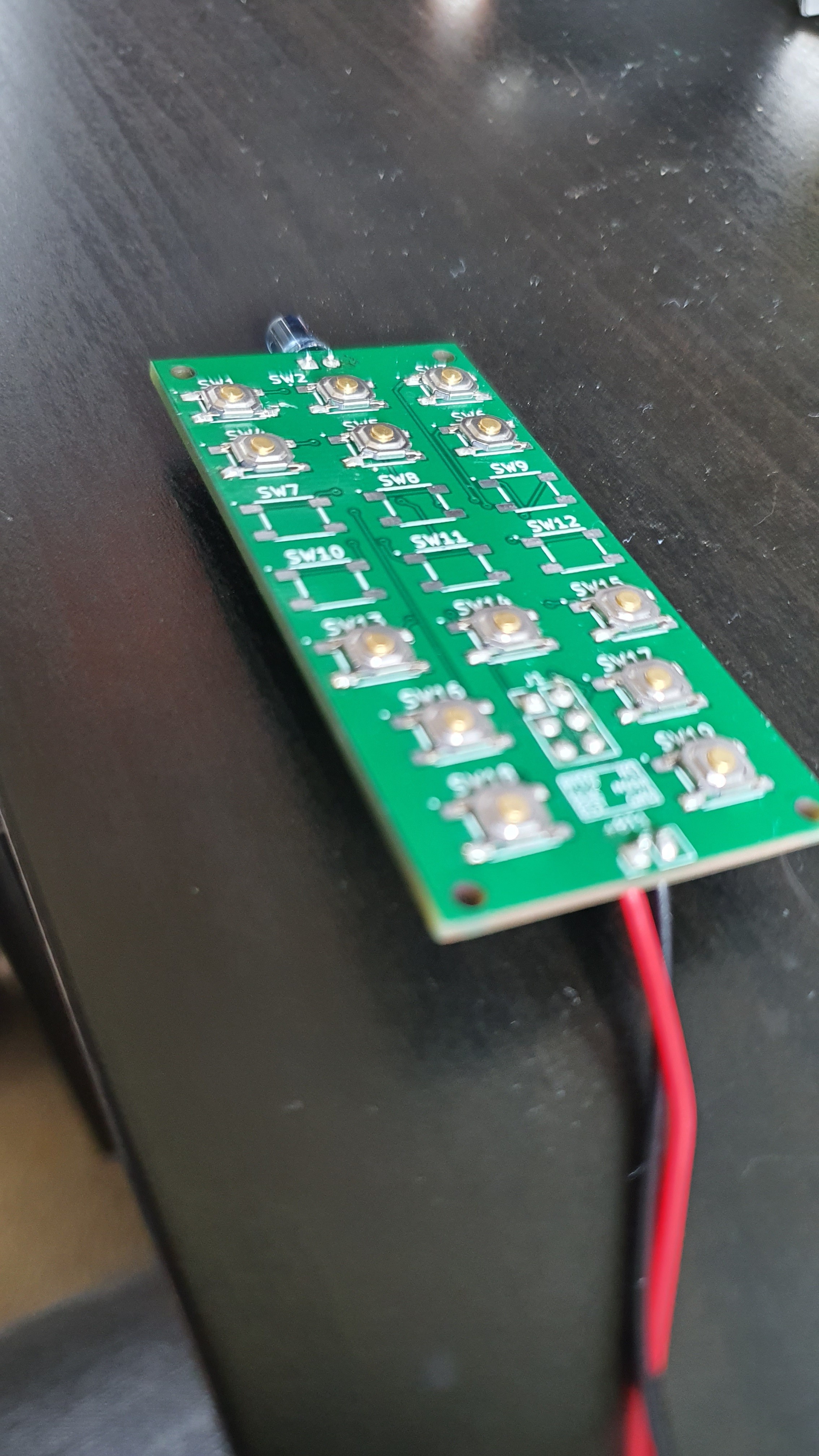
PCB order has arrived! I have built one circuit and it is programmed to control my Sony CD player. After a few issues (forgetting to set some pins as inputs and installing the wrong ATMEGA328!) it seems to be working well. Currently the enclosure is being printed and the hopefully it will be all ready to go.
As I am still in lockdown I have ordered the PCBs and parts which hopefully will be with me soon. I can then get the prototype up and running soon!!
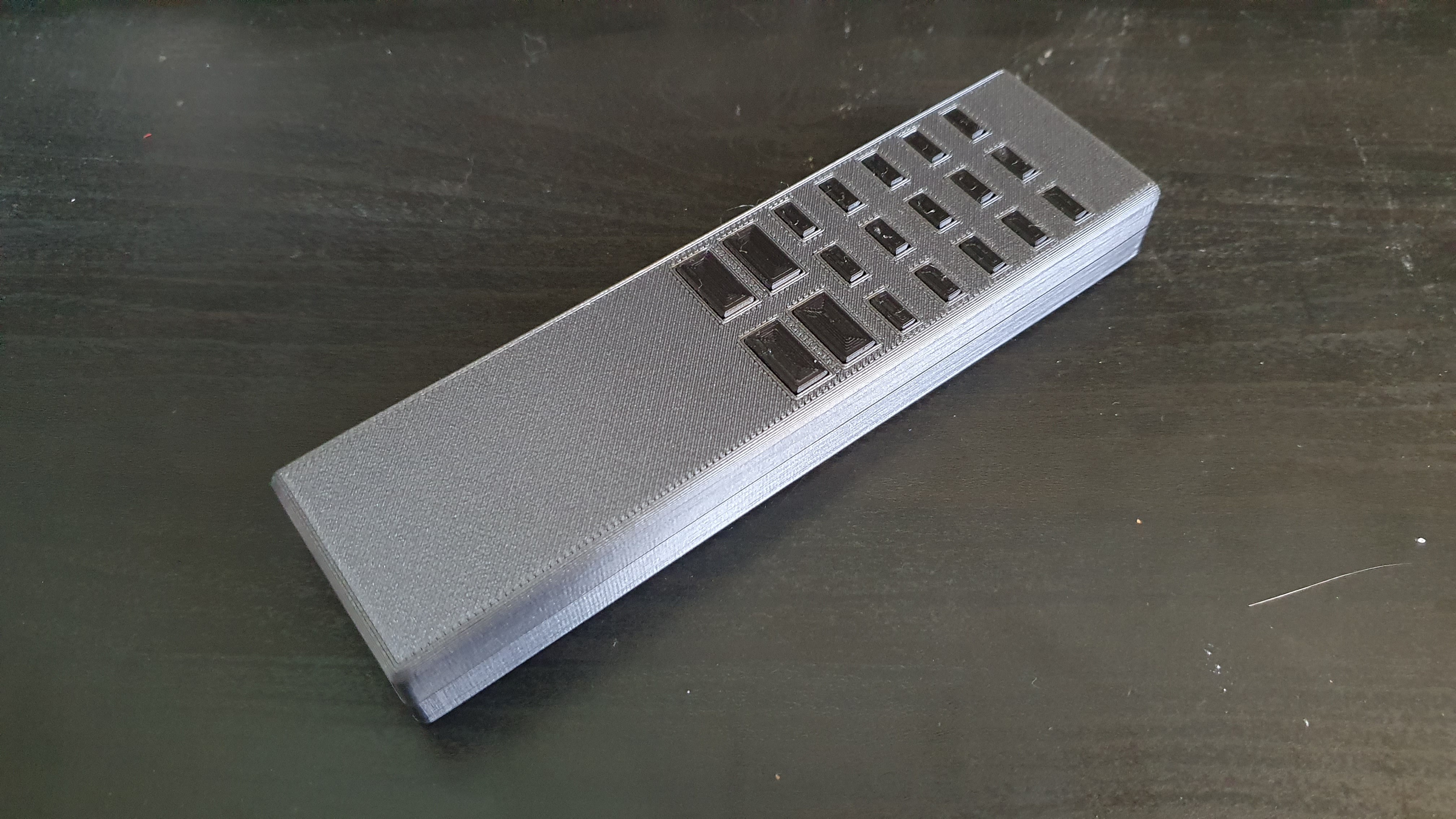
While I wait for the world to return to something resembling normality I have been working on the remote control casing. Here is a sample of the current design of the remote control casing with buttons. This model shows all the buttons that would be available, obviously fewer can be used, the reason I made this for my CD player only uses 12 of them so some will be blanked.
Create an account to leave a comment. Already have an account? Log In.
Thanks! Hoping to get this prototype once the current crisis is over :)
Become a member to follow this project and never miss any updates
Really like the idea of the sticker overlay for different applications. Makes for a very professional look.