 Samuel A. Falvo II
I've completed the initial design for the printed circuit boards for the RC2014 computer. This is my very first PCB design in KiCad, along with my very first 4-layer board, so I really have no idea what I'm doing. That said, I did it anyway, and the first batch of printed circuit boards have been submitted to OSH Park.
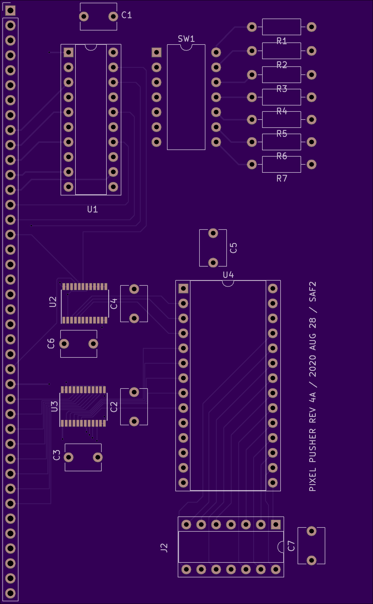
Nothing has been ordered yet, however. I'm waiting to hear back from OSH's support team on one question I had after uploading the designs. But, assuming everything checks out, I'll be placing an initial order for three circuit boards.
The circuit boards will make use of a 14-pin DIP socket as a connector for a mezzanine circuit board. This connector provides access to 11 digital I/Os on the FPGA, which is enough to drive an analog VGA port using discrete resistor DACs. The pin-out of the J2 connector (as it's currently labeled on the PCB) is as follows
| Description | Pin | Pin | Description |
|-------------+-----+-----+-------------|
| R2          |   1 |  14 | R1          |
| R0          |   2 |  13 | G2          |
| G1          |   3 |  12 | G0          |
| GND         |   4 |  11 | +3.3V       |
| B2          |   5 |  10 | B1          |
| B0          |   6 |   9 | n.c.        |
| HSYNC#      |   7 |   8 | VSYNC#      |
This pin-out supports a 512 color display. However, if you reprogram the FPGA for other tasks, it can be used to, e.g., control SPI or I2C devices, and so forth.
One pin is no-connect, and is intended to allow future mezzanine boards to auto-detect which version of the connector they're plugged into. For example, if a later revision of the video card supports 32768 colors, I'll need to add 6 more pins (at least). A 32K-color mezzanine designed for the 20-pin connector can still plug into and inter-operate with the older 14-pin connector, if it pays attention to pin 9. (Although, how it is to pay attention to pin 9 remains to be specified. YAGNI.)
Discussions
Become a Hackaday.io Member
Create an account to leave a comment. Already have an account? Log In.