Like any normal person, I want a desk clock that has sub-millisecond accuracy.
Parsing and immediately displaying time from NMEA messages as they arrive from the GPS module, like GPS Wall Clock originally did, gives a useable-enough value for display, but it's not particularly accurate for a few reasons:
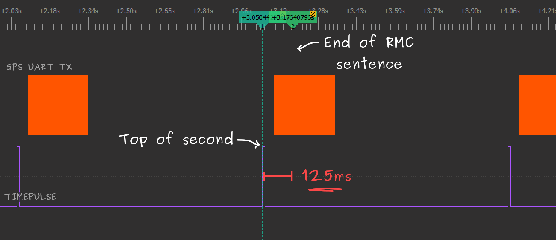
- The GPS module outputs messages at 1Hz, but each of these serial transmissions only begins once the GPS has finished its internal fix calculations. Fix calculations take a variable amount of time depending on the number of satellites being used in the calculation, which can be from 40 to 100ms for 1-12 satellites.
- At the default 9600 baud, a NMEA RMC sentence containing the current time will take 42 - 82ms to receive, depending on the number of fields filled.
- Converting the received time into segment data and sending to the MAX7219/MAX7221 over SPI takes some processing time.
To avoid these delays and uncertainties, the GPS module offers a TIMEPULSE pin that can be used to generate interrupts on our controller at the top of each second with considerable accuracy.

How accurate are we talking?
The u-blox documentation claims it's possible to get timing accuracy in the order of nanoseconds with ideal conditions, while accuracy in the order of microseconds is quite achievable:
As a rule of thumb the position should be known with an accuracy of better than 1m for a timing accuracy in the order of nanoseconds. If an accuracy is required only in the order of microseconds, a position accuracy of roughly 300m is sufficient.
Let's not get too carried away though - we're making a display for humans after all, where perception seems to take in the order of tens of milliseconds at best. In practice it will take someone much longer to look at and interpret the display.
Consider that in your day-to-day life, knowing the time to ±1 minute would likely be inconsequential, and ±1 second would be practically imperceptible. I would hazard a guess that the standard deviation of maintained time-keeping devices you encounter is at least 30 seconds, though I can't find anyone who has sampled this, and networked clocks probably tighten this guess up a bit.
I'm happy drawing a line at ±1ms, mainly because digging any deeper yields more and more uncertainty:
- What is the precision of the timepulse signal? (Something like ±30ns if the jitter and quantization in the module's 48MHz clock isn't compensated for)
- How quickly does segment data sent to the MAX7221 actually change the output signal? (The datasheet lists a maximum output propagation delay of 25ns)
- How fast do the LED segments actually light up? (It depends, but probably <1μS)
- How long does it take for light to travel from the display to your eyes? (about 3.3ns, if you're 1 metre away).
- ...ad nauseam ...
Given that I'm using these modules indoors and don't have equipment to verify absolute accuracy anyway, all of this is essentially academic, but it's fun to consider.
Using timepulse (1PPS)
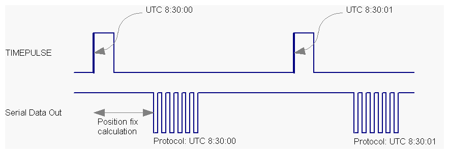
The TIMEPULSE pin on the GPS module generates a rising edge at the top of each second, with a configurable offset in nanoseconds to account for electrical and processing delays. Messages sent by the module always correspond to the previous timepulse, though the documentation only mentions this a few times briefly:

To display the time correctly, we'll need to calculate the next time to display when a NMEA "Recommended Minimum" (RMC) message arrives. At the following rising TIMEPULSE edge, this calculated time needs to be displayed. The MAX72xx will immediately update its display when any digit data is written, so the most I can prepare in my case is internally buffering segment data ready for blasting out over SPI.
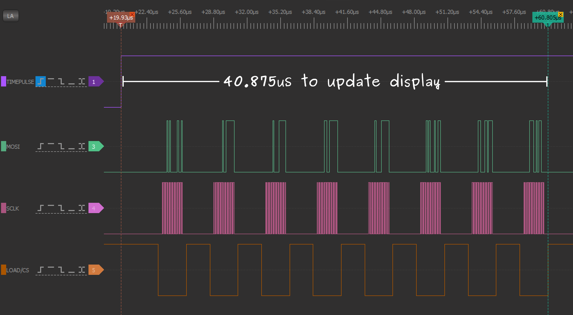
Due to the reversed wiring of the MAX72xx for common-anode digits on this project, all 8 "digit" registers always need to be written when updating any of the VQB-71 digits, even if only one digit has changed. This might seem like a disadvantage in terms of speed, but a consistent update time is actually better here as it can be compensated away using the module's user configurable timepulse delay setting.
A quick measurement of the delay between timepulse and a complete display update using a logic analyser gives a consistent value of 40.875μS (sampled at 200MHz):

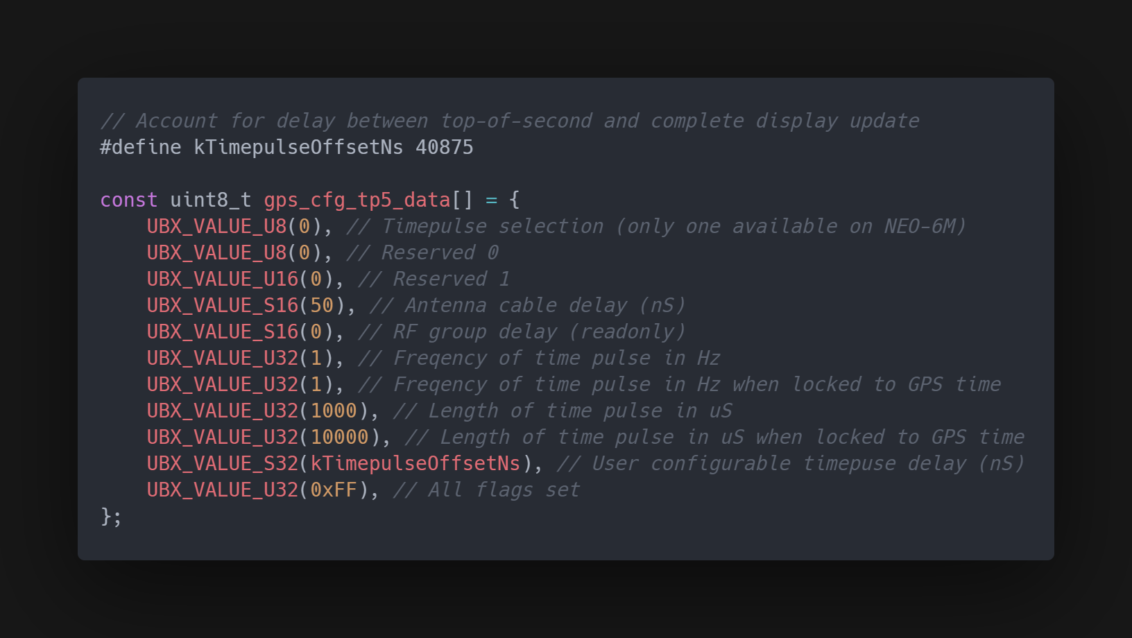
Configuring this on the GPS module requires sending a UBX protocol command - specifically CFG-TP5. The UBX protocol is binary, but it's well documented by u-blox and doesn't take much code to send commands. The data for my timepulse configuration command looks like this:

Note that timepulse is only guaranteed to be aligned with the top of each second if "GPS time is locked". As far as I can tell, a lock on GPS time doesn't necessarily require a position fix, but it does require the receiver to have a decent quality signal. NEO-6M modules in their default configuration won't output the timepulse signal unless GPS time is locked, but this can be tweaked using the CFG-TP5 UBX command, as I've done here.
If you don't want to write any code, these GPS modules can be connected to a computer by UART and configured using the u-center tool (Windows only) from u-blox.
Further reading
As mentioned, the official documentation for these modules is very good:
- u-blox 6 GPS modules datasheet (NEO-6)
- u-blox 6 Receiver Description including UBX and NMEA protocol specifications
- GPS-based timing considerations with u-blox 6 GPS receivers (app note)
- NEO-6 hardware integration manual
Since writing this article, I've also applied the same timepulse upgrade to the ATTiny-based wall clock - surprisingly managed to make it fit!
 Stephen Holdaway
Discussions
Become a Hackaday.io Member
Create an account to leave a comment. Already have an account? Log In.
Very cool project. I am using a NEO-6M for time acquisition and MAX7219 for display and I learned a ton from this post. Thanks for sharing!
Are you sure? yes | no