 danjovic
Some pictures of the assembly. First thecomponents
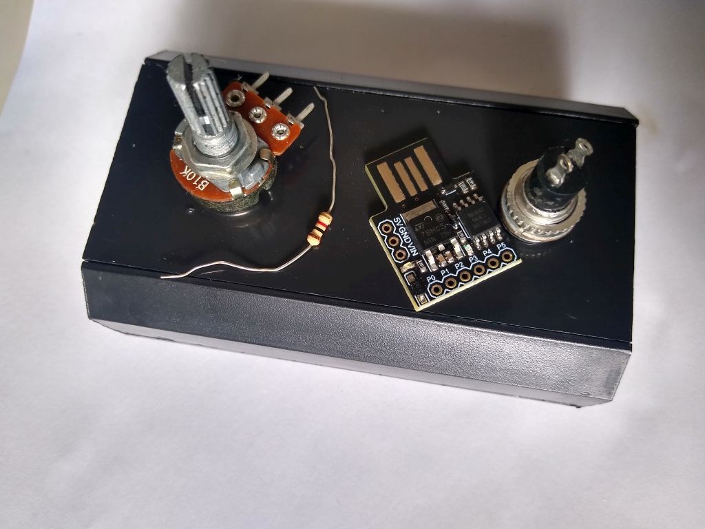
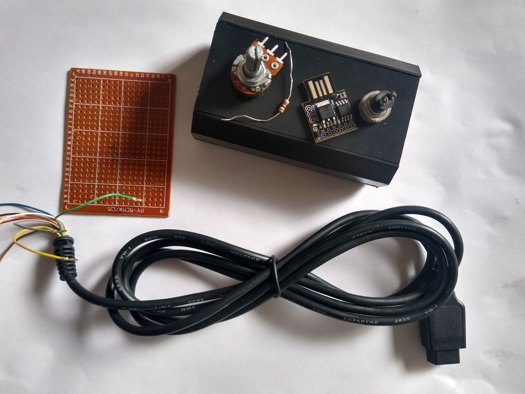
Another picture of the components. I have considered to use the Veroboard but haven't did that now. Maybe on the next project.
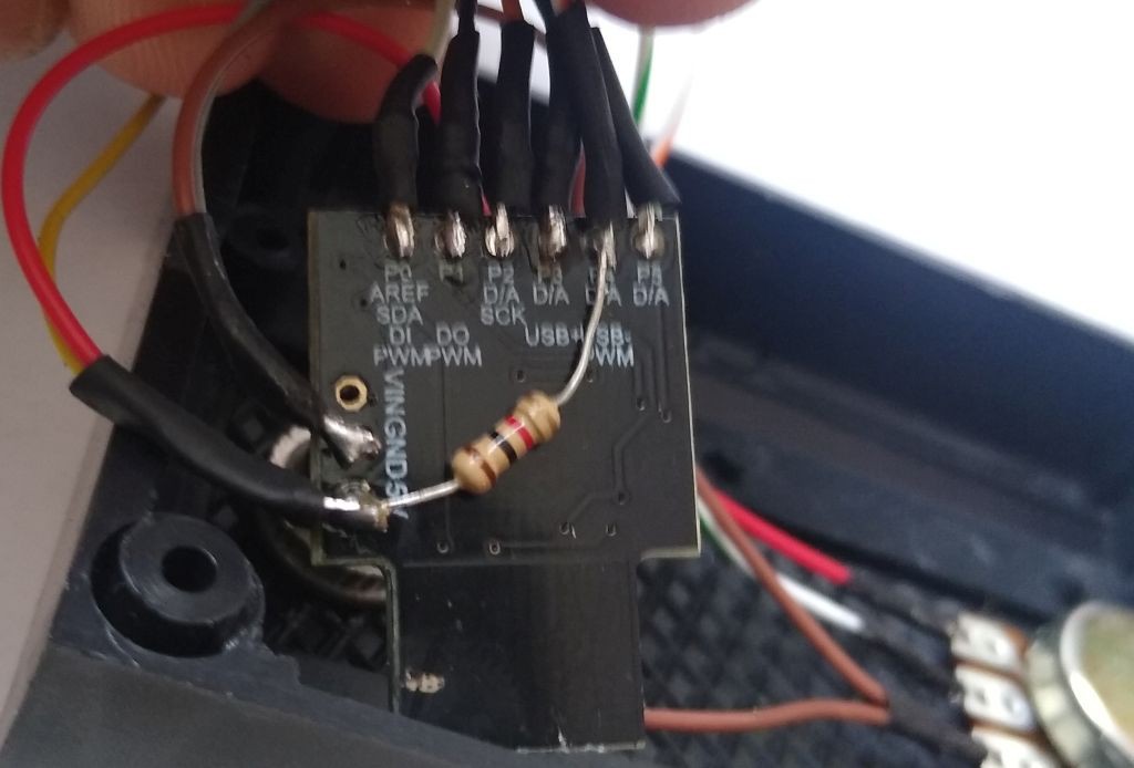
The resistor is soldered under the board, from VCC to PB4
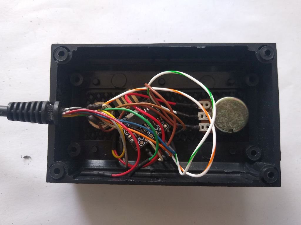
 Everything wired
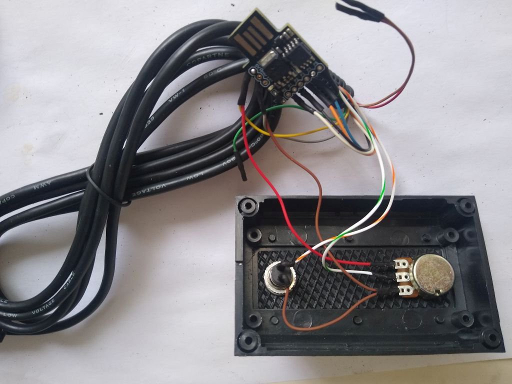
Wires organized
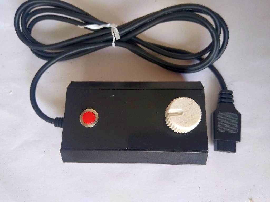
Unit assembled and closed
Discussions
Become a Hackaday.io Member
Create an account to leave a comment. Already have an account? Log In.