
Hardware
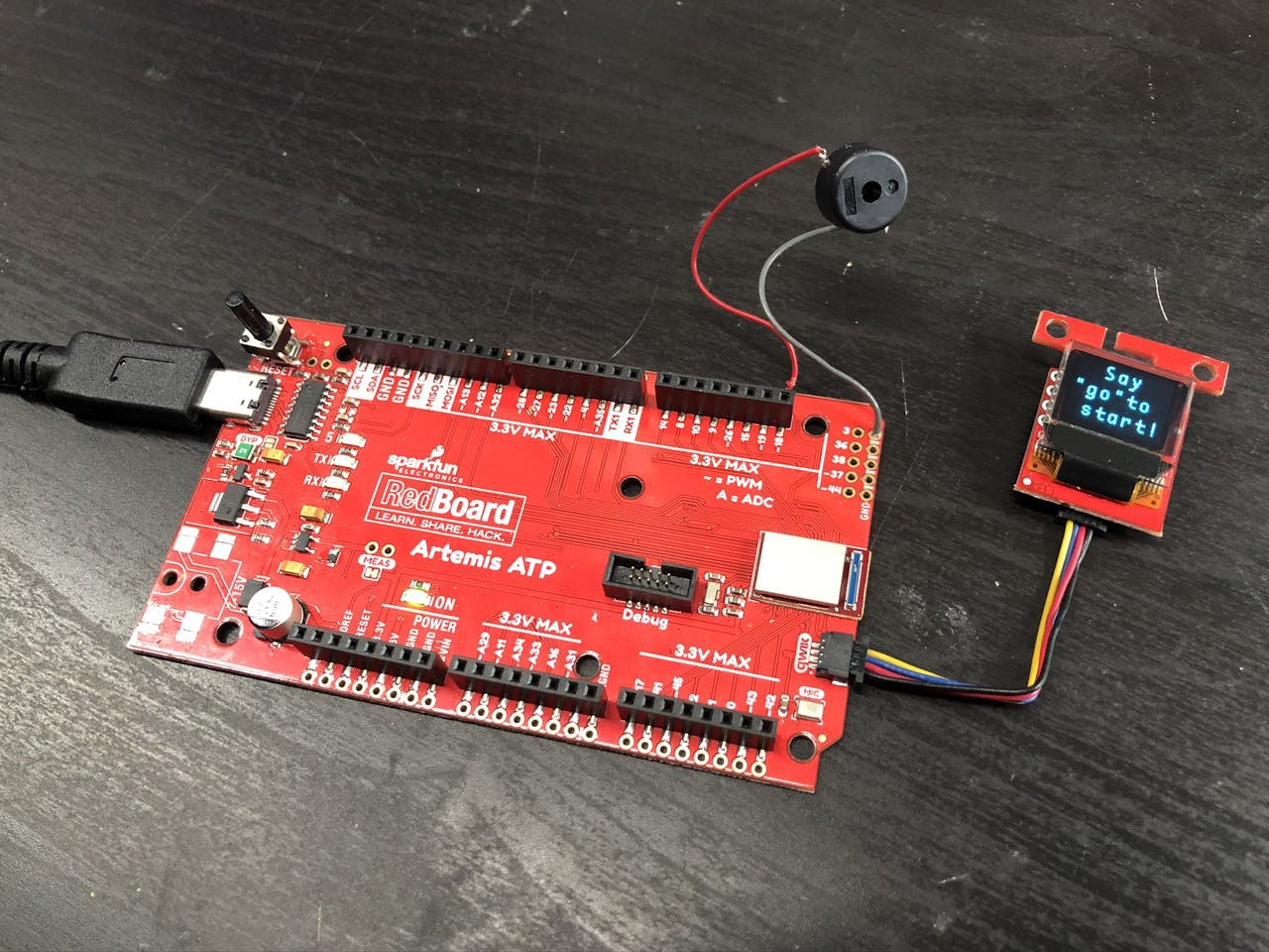
The two required pieces of hardware required for this project are a SparkFun RedBoard Artemis ATP board and a SparkFun Micro OLED Breakout (Qwiic). I've added a few more items and modified the board to improve the experience, but the whole project could be recreated without even using a soldering iron. SparkFun's Qwiic Connect System makes it really easy to work with these items. Just connect the items with the premade cable and everything will work.
I added a buzzer which produces a unique tone for each of the four directions. This isn't necessary, but it does provide a slightly more polished experience. An idea that I didn't get the chance to implement is to add LEDs that also relate to the four directions (I recommend a red, yellow, blue, and green LED to mimic the original design). An enclosure printed in transparent filament would work well to diffuse the LEDs. The software could also be extended to play tones or make light patterns in response to different states like the startup screen or the game over screen.
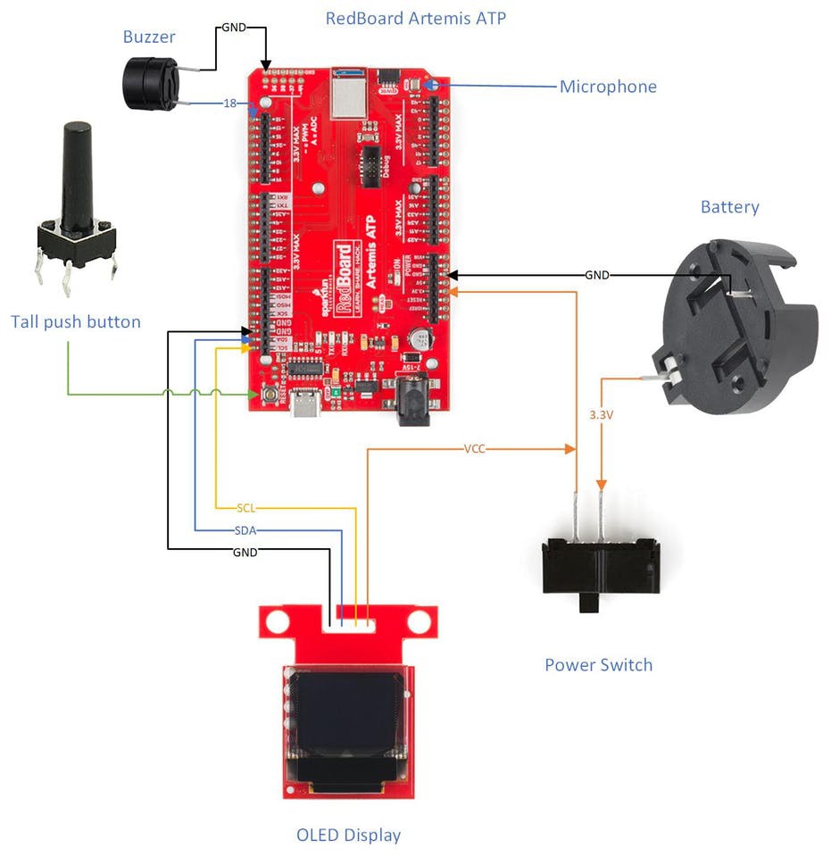
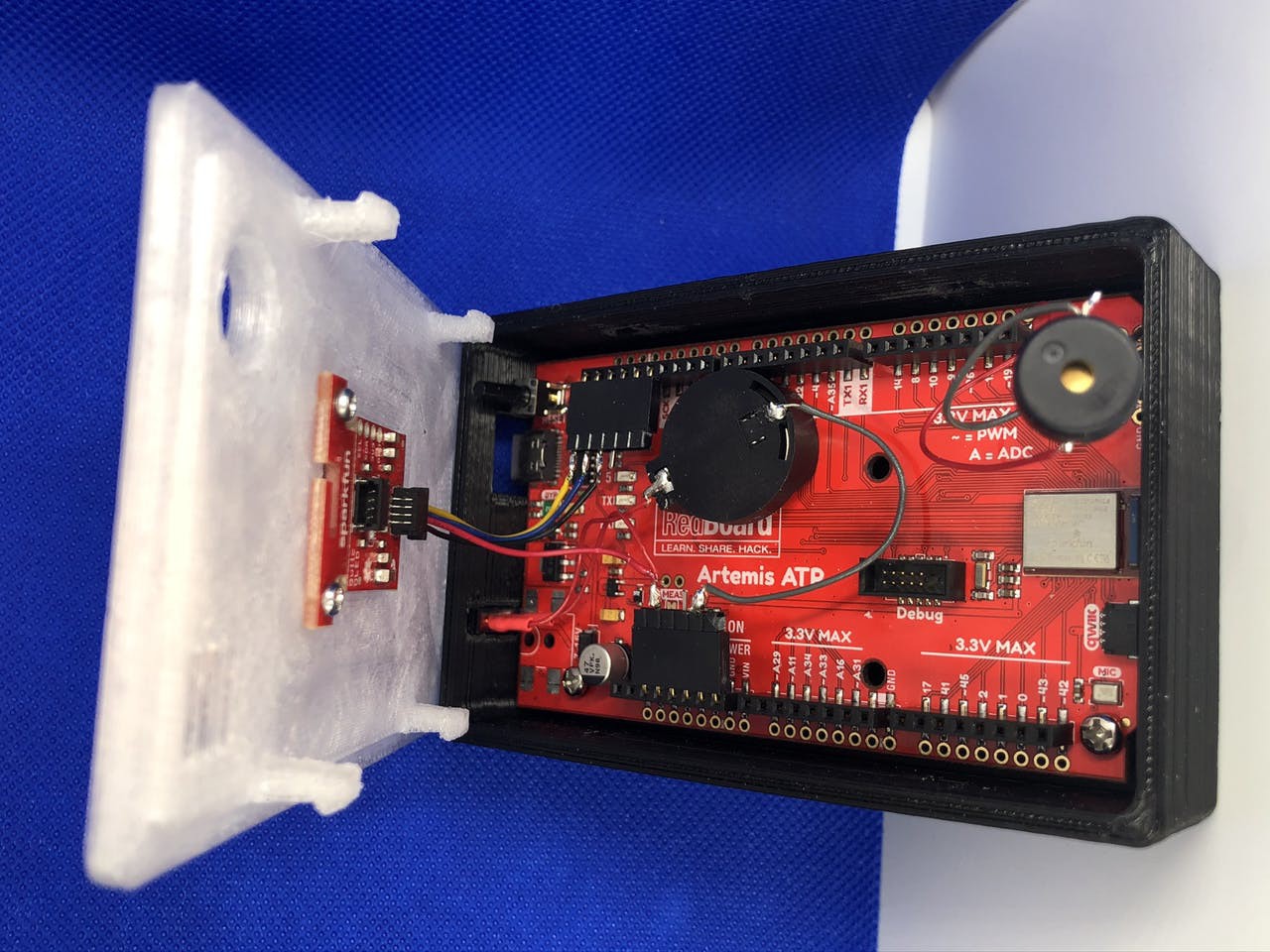
I had to make few modifications to the board due to my enclosure design (which will be discussed in the next section). The biggest change that I made is the removal of the power jack to make room for a power switch. The game draws about 9 mA while running and goes into a low power mode after quitting which drops the power usage to about 6 mA. This is higher than I expected so I think I could make some more optimizations to drop it even further. I added a different type of button to the board to extend the reset button outside the enclosure, which takes the board out of low power mode and starts another game. I used a different type of battery holder because I didn't want to mount the battery to the back of the board and make the enclosure larger. I added a hard power switch inline with the battery for when the game isn't going to be used for an extended amount of time. My enclosure didn't leave room to use the Qwiic connector on the board, so I rewired the cable directly to the pins instead.
Enclosure
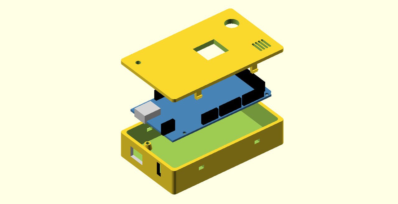
My enclosure is based on the Arduino OpenSCAD mounting library (v2.0). I really enjoy using OpenSCAD to design simple enclosures, so I was thrilled when I found this library. After printing out my first revision of the enclosure, I realized the RedBoard Artemis ATP is not the standard size for an Arduino Mega so I had to hack up the library to make it fit. I spent a lot of time trying to do it the right way, but then I realized it wouldn't really give me the result I needed.
A major design constraint is the limited size of my 3D printer bed. My longest axis is 112 mm wide and I managed to squeeze the enclosure into 111.6 mm. This is the reason that I needed to rewire the display -- I just didn't have room to extend the enclosure so that I could use the Qwiic connector.
The mounting holes on the board lined up, so I just had to make the enclosure wider for the wider board. I modified the USB hole to go from a Type B to a Type C with room for the cable I have. I modified the power jack's hole so that it fits the power switch snugly.
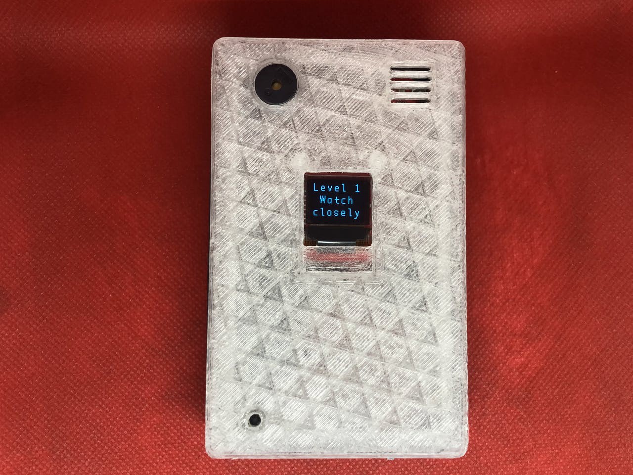
The lid was also modified to make it as wide as the enclosure. Besides that, I added holes for the reset button, buzzer, display, and microphone. The display is mounted with screws to the bottom of the lid. I made a speaker grill design so that the microphone can still hear me.
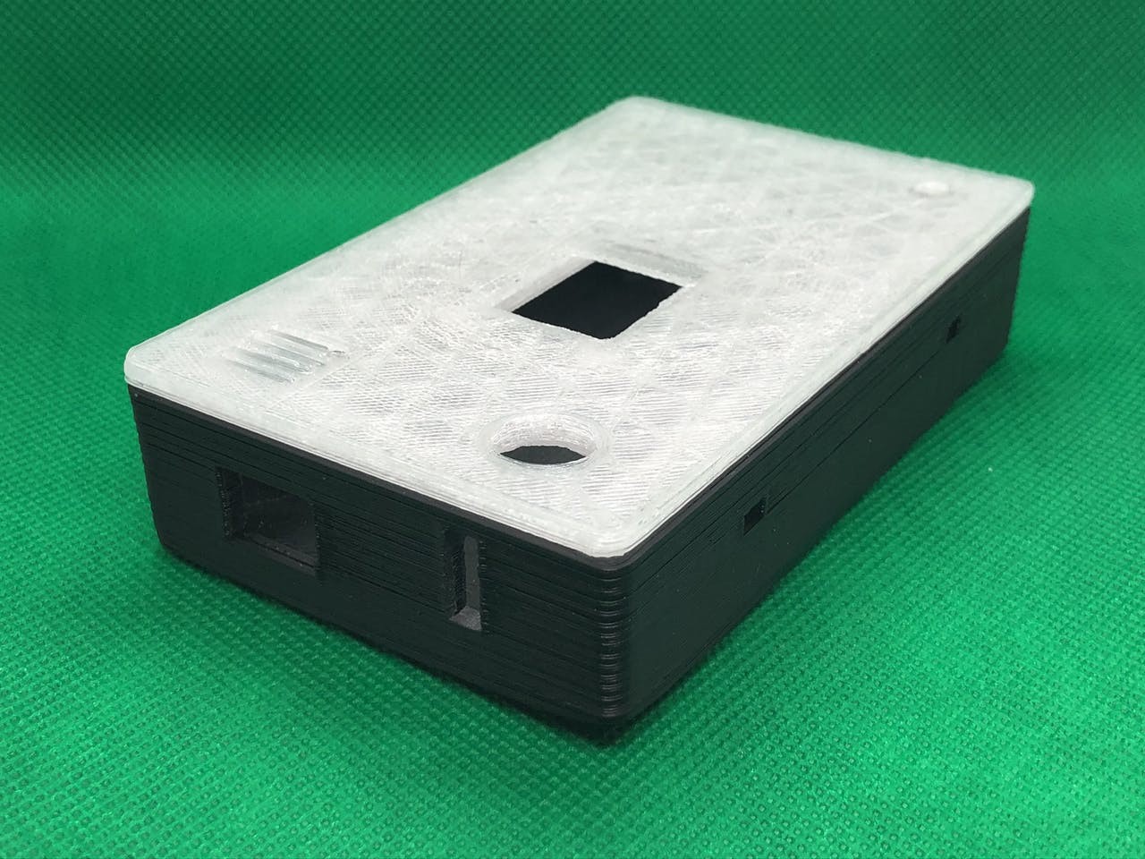
You can find my source files for the enclosure on my GitHub (specifically enclosure.scad) or Thingiverse (includes some extra photos).
Software
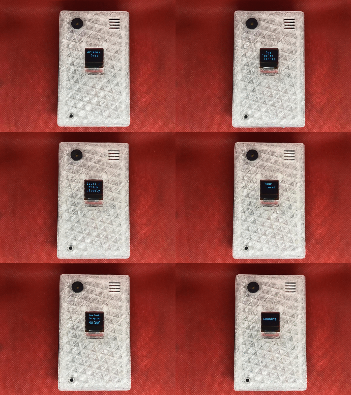
There are two different development methods for the Artemis module: Arduino or the Ambiq Apollo3 SDK. I thought the Ambiq SDK was required to use Tensorflow, but after having a lot of trouble setting it up, I found a project that uses Arduino and Tensorflow. My project is based on the ArtemisATPTensorflowMicroSpeech project...
Read more » Dillon Nichols
 Jean-François Poilpret
 jareklupinski
 Dylan Turner
 WJCarpenter