 Tim
TimIn parallel to building the ring oscillator models I also implemented the same in LTspice. You can find the files files on the project page. Please find a very brief summary below.
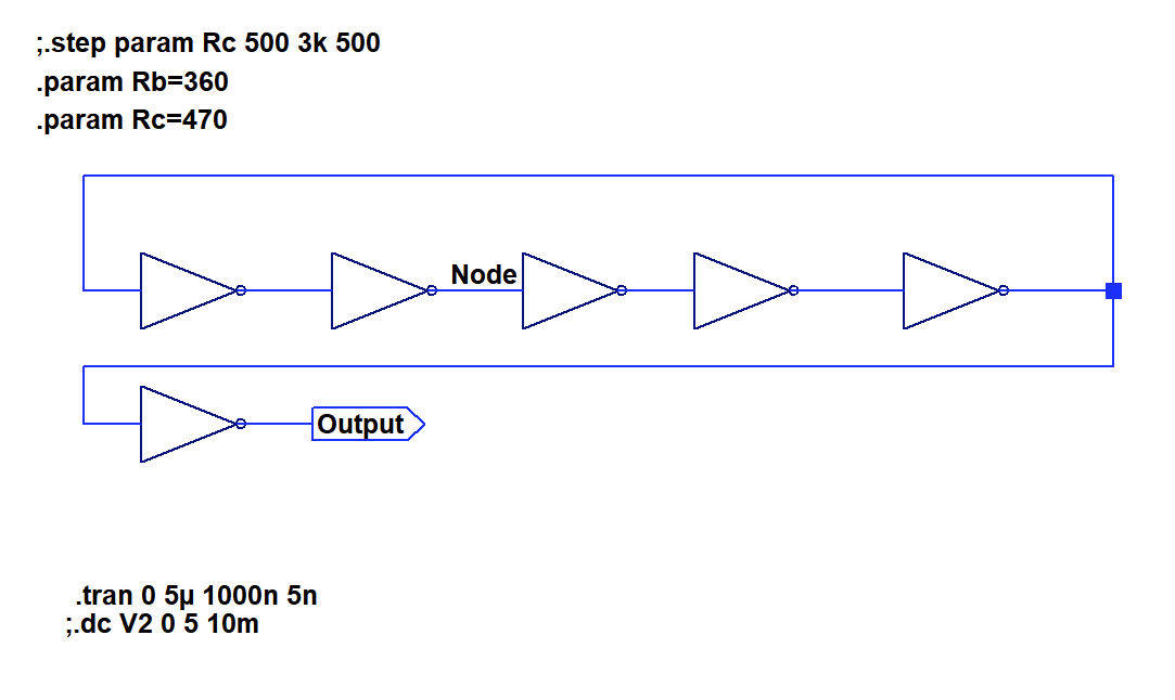
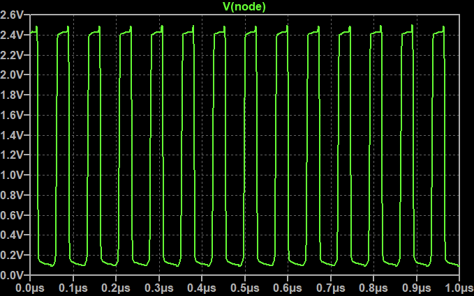
I implemented a 5-stage ring oscillator with an output buffer. Same circuit as on the PCB.. Using the transient function, it is possible to investigate frequency and waveform.
To test the transfer function, I used the DC sweep function in the circuit below. Since the loading of the output has a significant influence on the output voltages of an RTL gate I looked at both loaded and unloaded output.
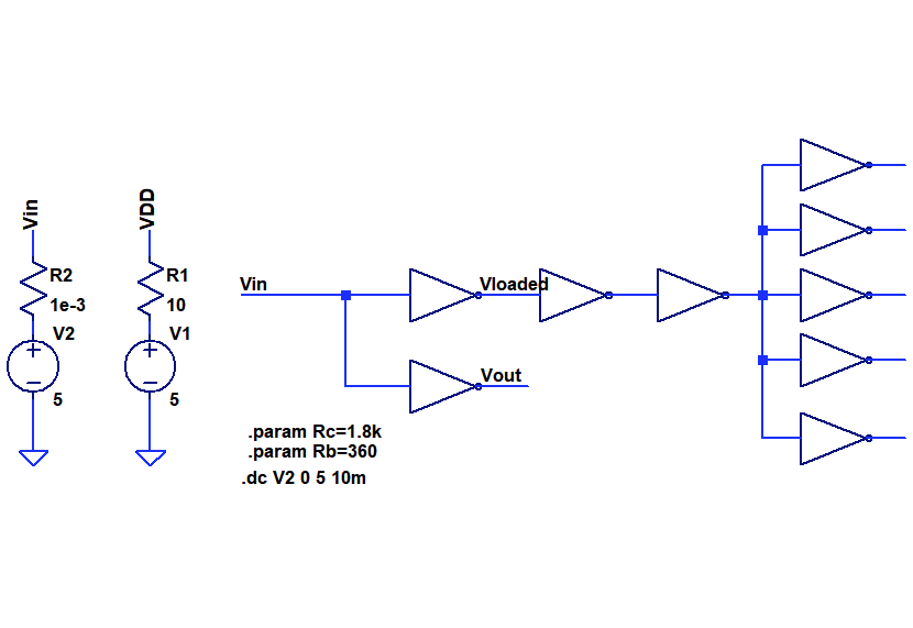
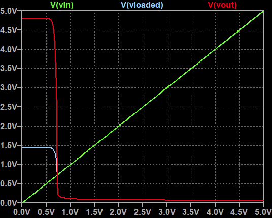
Sweep output shown below.
An inverter circuit is shown below. As you note, I also did some experiments with a reach through capacitor.
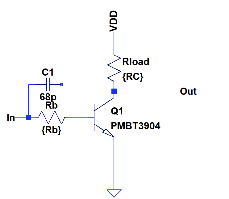
Resistor variation on the PMBT2369 based inverter
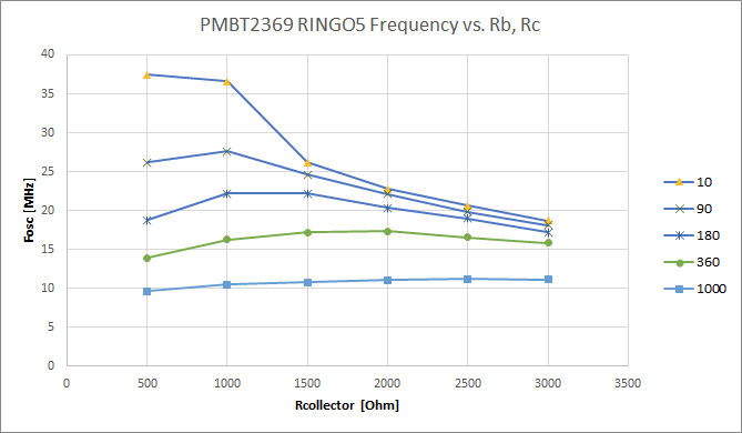
I used the ring oscillator model to investigate the impact of base and collector resistor on ring-oscillator frequency and hence propagation delay. the graph below shows the collector resistance on the x-axis and various plots as a function of base resistance.
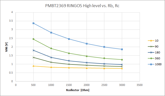
Impact on logic levels.
Discussions
Become a Hackaday.io Member
Create an account to leave a comment. Already have an account? Log In.