 Tim
TimSo, we established that the PMBT2369 is the fastest saturation-switching transistor available today and that it achieves a minimum propagation delay of 3.5 ns at a bias current level of 10 mA. How can we go further from there? Obviously, more brute forcing by changing resistor values and increasing currents is not the way to go. Alternatively we can add components to the basic RTL gate.
There are two approaches: Adding a reach-through capacitor in parallel to the base resistor and adding a baker clamp.
Simulation
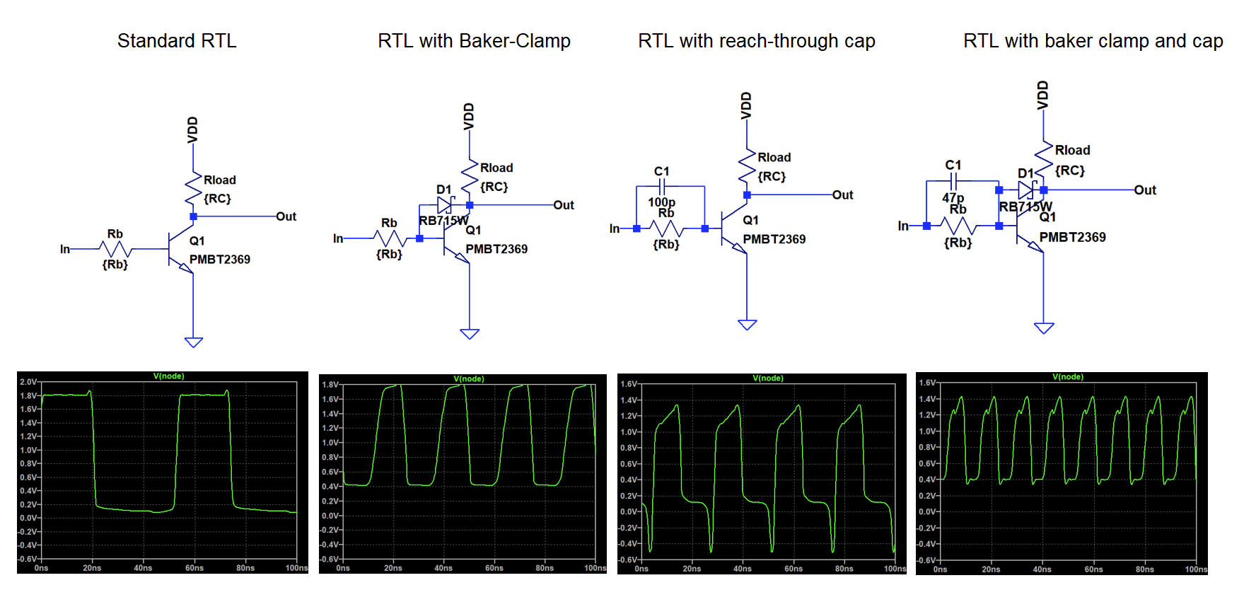
The panel above shows circuits of both options individually and in combination including the resulting waveformt of the ring oscillator.
The reach through cap basically shorts the base resistor for high frequency components of the input signal; the rising and falling edge. For the critical case of a falling edge of the input signal it will lead to negative biasing of the base, which will help to remove the saturation charge. You can see above, that it even leads to a negative spike of the output signal due to coupling to the collector.
The baker clamp prevents saturation of the transistor by shorting the base with the collector if the base potential is too high. The choice of the diode is quite critical here: A schottky diode is needed to minimize forward voltage and the capacitance needs to be lower than CBC of the transistor to avoid excessive miller capacitance that could limit the turn-on time. Since the baker clamp shorts the base to the collector, also the low voltage level is increased to about 0.4V. Therefore, noise margin is drastically reduced for this solution, something that is not preferrable considering the already low noise margin of RTL.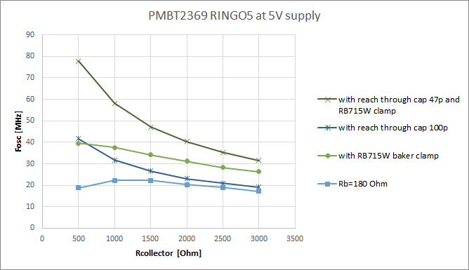
The reach through cap works best, when the voltage drop across the base resistor is high, because this leads to a stronger negative overdrive of the base. This condition is optimizated when Rb is large compared to Rc, as is evident for the strong increase in frequency for lower collector resistance in the plot above.
Hardware testing
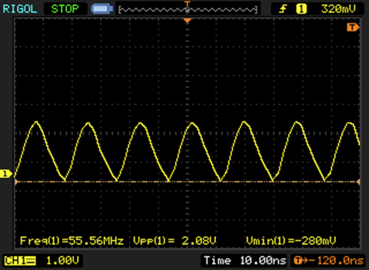
Due to lack of suitable schottky diodes I was only able to test the reach-through cap in real hardware.
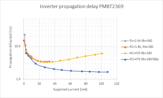 Finally, looking at the bias current / tpd trade off, we can see that the seemingly unsurmountable trend of pure RTL has truely been beaten and less than 2 ns tpd is achieved at higher current. Quite an astonishing result for discrete saturation logic!
 There are some caveats: Keep in mind that the full oscillator is supplied with more than 1 W of power at this operating point, almost 200 mW per gate. Collector bias of a single gate is ~30 mA and the PCB is getting notably hot. Furthermore, since the input to the gate is basically a high-pass, the propagation delay of the gate will be dependent of the slew rate of the incoming signal. This adds another dimension to the complexity of logic design.
Discussions
Become a Hackaday.io Member
Create an account to leave a comment. Already have an account? Log In.
Probing idea !
You could try to measure your signal directly on the high side of the circuit (so you need a floating ground) and put your 'scope input directly in series with the 470 ohms pull-up resistor, and set the input to 50 ohms (and use a suitable coax cable)
I'm eager to test that circuit on my Tek scopes :-D
Are you sure? yes | no
That's an interesting idea, indeed. I guess you would also have to terminate the input. Seems a bit scary in regard to the current requirements, though. But alas, it seems my scope does not support 50 Ohm input. It's a lowly Rigol 1052E hacked to 100 MHz.
Are you sure? yes | no
oh :-/
I hope you are lucky as I was when I found a Tek 2465 in good condition for about 400$ on eBay.
Look for 2465, 2467, 2465B, 2467B, you will love it ! 300MHz or more, 4 channels, intuitive interface, a pleasure to use :-) (but it's analog so you can't make digital screenshots)
Are you sure? yes | no
did you plot a curve of the effects of the capacitance value ?
Are you sure? yes | no
no. Unfortunately it's not possible to automatically measure frequency in LTspice. So any kind of sensitivity analysis is quite tedious.
Are you sure? yes | no
I can't wait to return to the workshop, check my stock of parts and try by myself...
Thanks again for the inspiration :-D
Are you sure? yes | no