 makufelis-xyz
With not much left to do here I assembled the final LED boards. After hooking them up I noticed that some of the LEDs had a slight tint towards blue which I'm pretty sure is a consequence of overheating while soldering so definitely something to take into consideration for later assemblies.
Another thing I did was to calibrate the RTC clock so it runs in tune with the atomic clock. Since this clock doesn't have WiFi or GPS syncing ability the calibration is a must IMO.
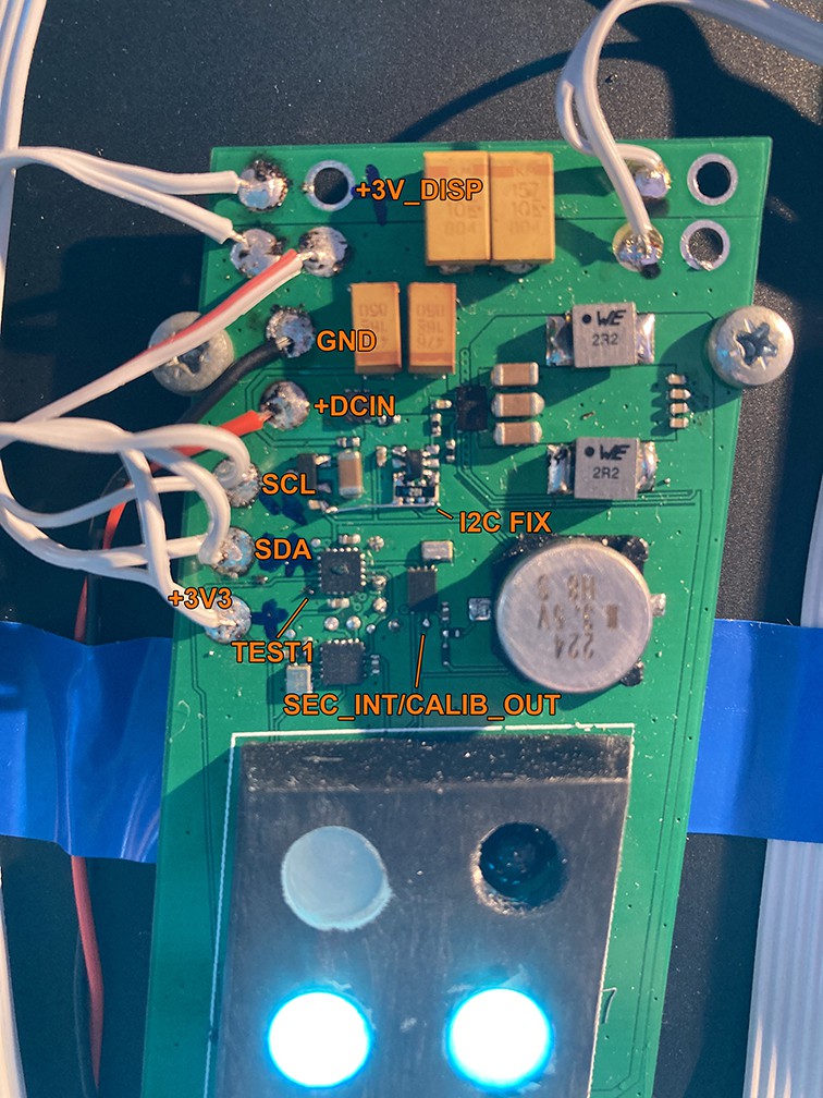
So to calibrate the RTC i connected a frequency counter to SEC_INT/CALIB_OUT and held TEST1 low. That way the clock entered calibration mode where the RTC chip outputs its current running clock of 4096Hz at SEC_INT/CALIB_OUT and I could compare it to reference clock of 4096Hz and then calculate the deviation in ppm.
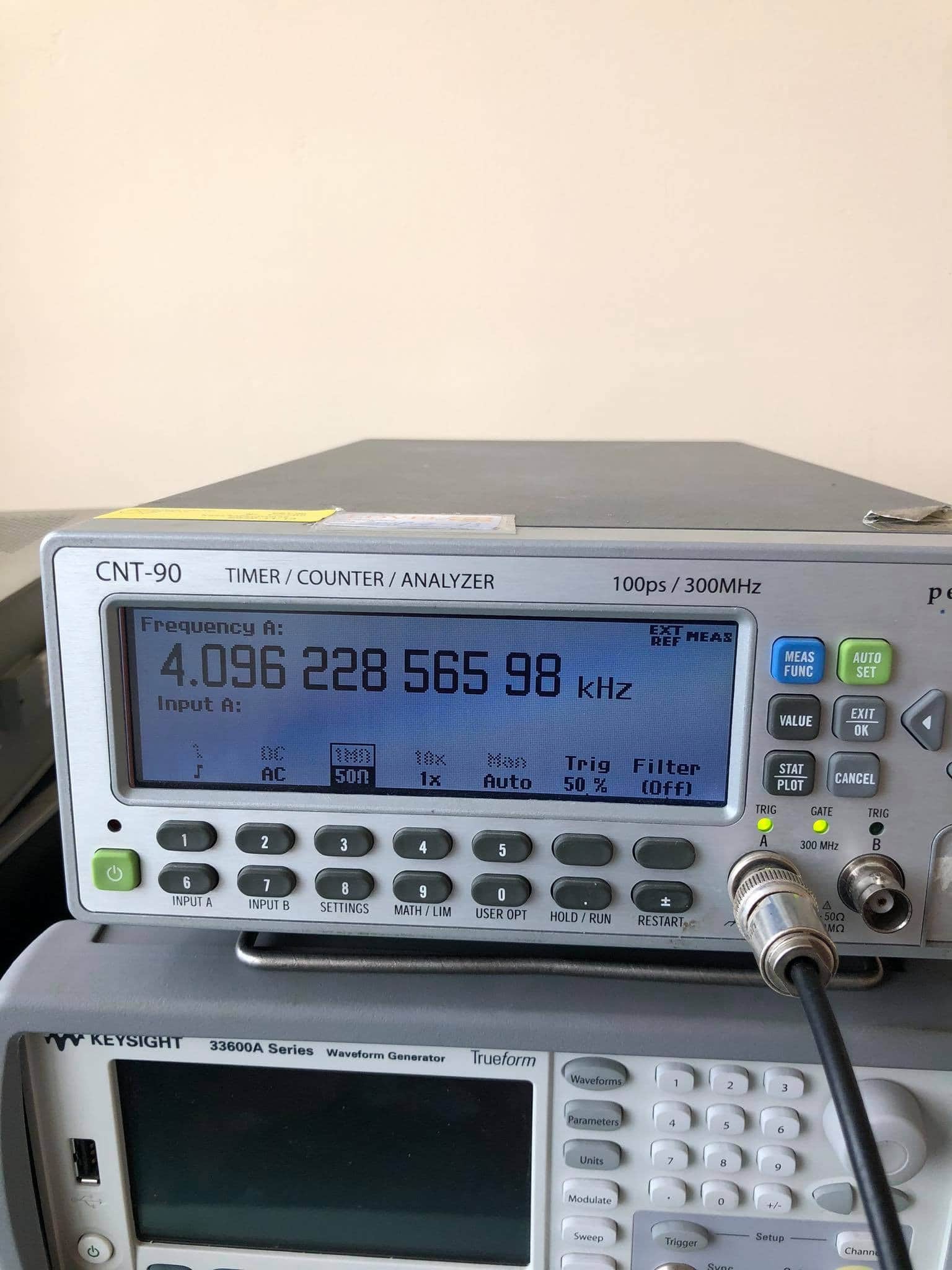
So the clock was speeding at +55.8ppm which might in part be a result of me not putting any crystal capacitors which makes the crystal frequency go up but it's fine.
Oh, and I made the typical rookie mistake of not putting in I2C pull-up resistors in the schematic so I had to fix that.
Discussions
Become a Hackaday.io Member
Create an account to leave a comment. Already have an account? Log In.