-
Bubble Buying - Tips and Warnings
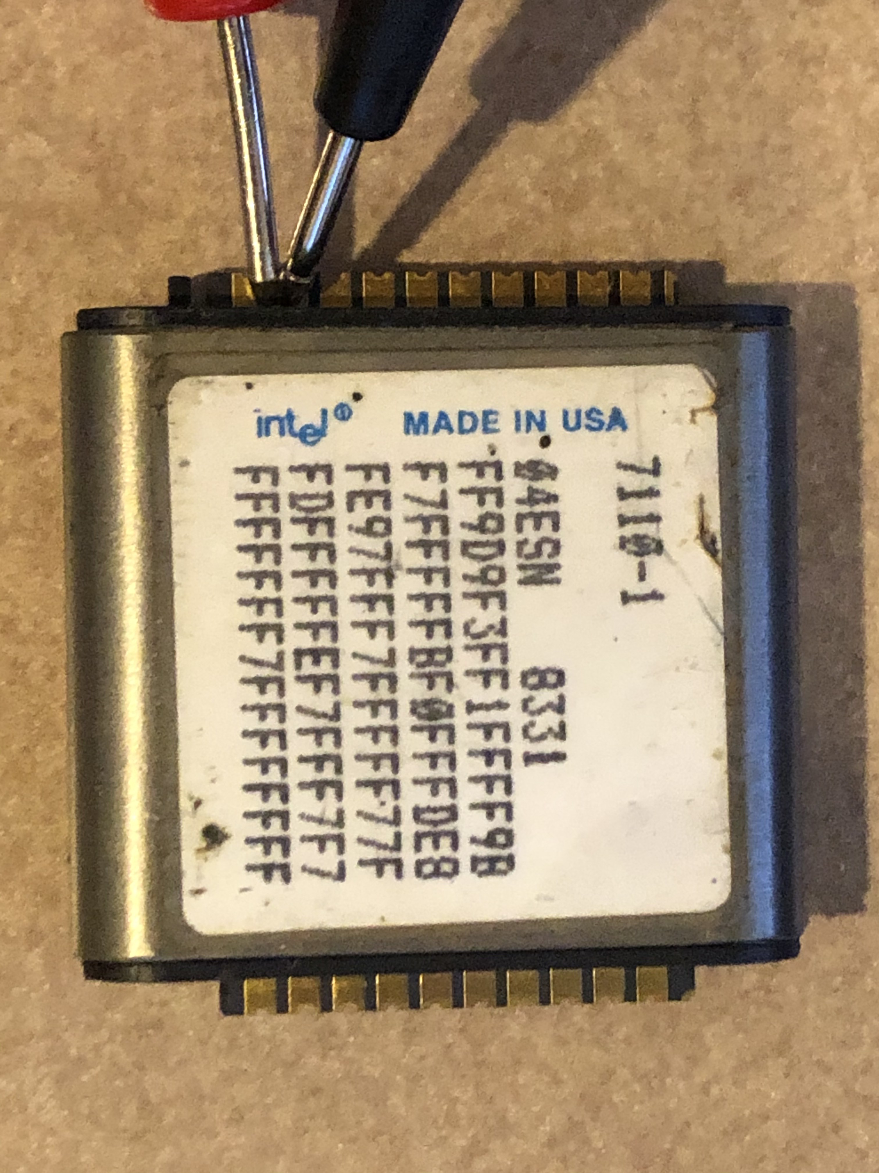
05/25/2020 at 19:56 • 0 commentsCurious about the condition of bubbles that I have seen available for sale, I decided to take the plunge and buy a few of the reasonably priced bubbles to get an idea of the risk level of buying used bubbles. I purchased some that were loose 7110 bubbles, with the typical 'working, removed from service' which of course means nothing since it is doubtful the seller knows their history, doubtful they were tested, and doubtful the seller knows if they are working. Of the three of these I purchased from different sellers, one worked, one was completely dead, and one had its boot loop erased. I have not reseeded and restored the boot loop on #3 so the jury is still out. On subsequent reads the boot loop gives different results, so the chances of that one actually being good are slim since the boot loop should always be consistent even if it is wrong. The one that was completely dead did not even ohm out properly. I can not imagine what it takes to completely destroy a bubble, perhaps it had a manufacturing defect and has been sitting in a junk pile ever since.
So for loose, 'removed from service' 7110s, the success rate was not good to say the least.
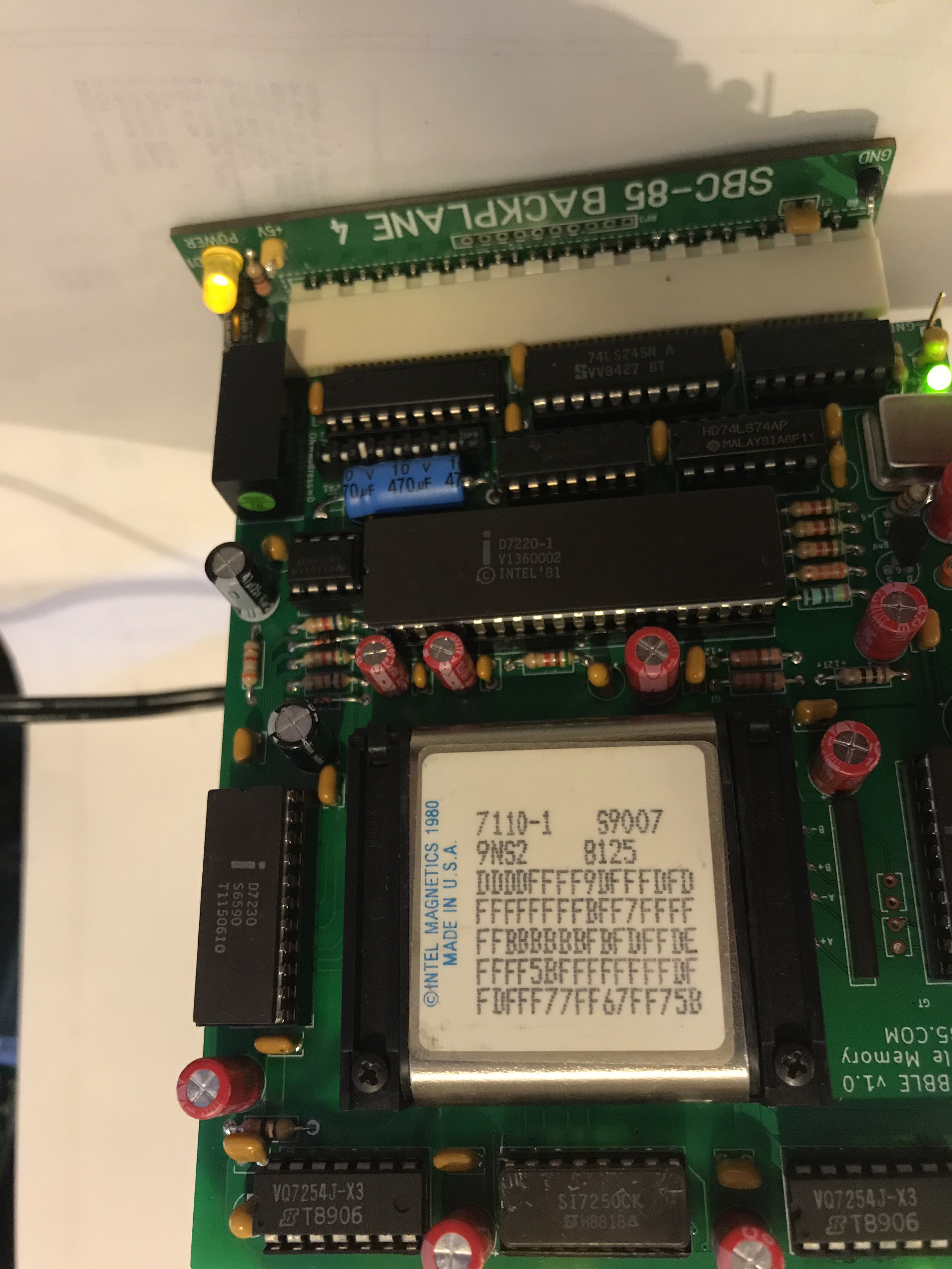
I have had better luck with bubbles that were still mounted to a circuit board. I have purchased 4 of those which I removed from their boards, did a resistance check, and installed in the SBC-85 bubble board. I am happy to report that all worked including boot loops and seed bubbles.
The results of this very small sampling are about what you would expect from any electronic device. Those removed from the board and having to endure the hard life of an unprotected, ungrounded, and mishandled chip have a much lower chance of surviving than those left mounted to a board.
-
My Bubble's Back and There's Gonna Be Some Trouble
05/17/2020 at 20:52 • 0 commentsHey-laaaaa. Day-laaaaaa. My bubble’s back
A quick update on the 7110A bubble board that arrived from the PCB fab shop and is now under test. This version of the board uses the much more common 7110A 20-pin version of the bubble. In addition to the device swap, the board also has more bulk capacitance to meet the voltage decay requirements, a few relatively minor patches were applied, and some cosmetic component placement changes. All-in-all, nothing that should break the design.
The short version is something is fishy because I cannot write to the bubble; or at least it will not read back what I have written.
I started diagnosing today and this is where I am now–
I can access the 7220 controller and it is giving me good responses to my queries as well as successful FIFO reads and writes. So at least I know that all is good in communicating with the bubble controller.
As the next step, I demonstrated to myself that I can read the boot loop and the values match the loop table the label. So that tells me that the rotating field is fine, the amplifier is good, and at least some of the signals from the pulse generator are OK.
Next I was able to write to the bootloop register (remember, you generally don’t want to be writing to the bootloop itself) and then read back this data. That tells me there is successful 2-way serial communcation with the formatter /amplifier.
If this board were for the 7110-1 leadless version to match the prototype, it would be a simple matter of swapping the bubbles to see if I have a read problem or a write problem (or both). I am fairly confident it is not a read problem since I am getting the boot loader correctly. So now it will be back to the oscilloscope to check for the waveforms from the pulse generator.
This is a new bubble from a BPK-70A kit that I have had on the shelf for years so I can’t imagine that it is a bad bubble. However, in the back of my mind I have to wonder if there is any way this device could have lost its seed bubble. If it is the seed, that will cause some delays since I will need to write some more code and build a bubble generator board.
Next up, I need to check everything from the pulse generator. If those all check out, then I need to seriously consider that this is a seed bubble problem.
Wish me luck, I will let you know when I find the problem but wanted to give an update on the status for anyone interested.
UPDATE 5-16-20: Got it. Details to follow.
regards
Craig
-
Catching up with Documentation
05/01/2020 at 00:50 • 0 commentsI have posted the schematics and software utilities for the bubble board on the SBC-85.COM project website under the Documentation tab. and will continue uploading and (continuously) updating the remaining documentation and eventually the gerber build files. Look now if you want a sneak peek at the documentation, however it will take me a while to flesh out everything including the BOM and all the details, so check back for a newer version now and again. Version 1.1 of the 7110A bubble board is already in the mail and hopefully I did not make any embarrassing mistakes when making the relatively minor updates from v1.0 and switching to the 7110A 20-pin.
I have contacted some people (repair houses) that I suspected would have bubbles, and indeed there are 7114As out there and somewhat available; but there is more than an order of magnitude variance in price. If you are planning on building bubble board, you may not want to buy the first 7114A bubbles you come across. These are for new old stock, or removed from service, tested, and known good bubbles from repair houses, not just some random bubble on the internet.
As always, let me know what is missing from the documentation, what is not clear, and what is outright incorrect.
regards
Craig
-
Bubble 7110A Ready For The PCB Fab House
04/24/2020 at 03:17 • 0 commentsThe first “real” version of the SBC-85 1 Mbit bubble board is about ready to go to the fab shop so they should arrive back here mid May. The 7110A is the 20-pin version of the bubble, not the leadless version that requires the carrier used in the prototype board. Since the 7110A version can be found for sale much much more frequently than the leadless 7110, AND because the Molex carriers do not exist anyway, AND because the board needed room for more bulk storage capacitance to meet the power off voltage decay rates, version 1.1 is designed around the 7110A bubble. The 7110A is functionally equivalent to the original 7110, just Intel’s “updated” packaging.
The 20-pin 7110A followed the release of the 4 Mbit bubble which was only ever released in the 20-pin version. As a matter of interest, the original leadless 7110 package was released as a stopgap because they were having technical issues with the epoxy injection moving / destroying the bonding wires. The problem was solved when they went to a newer low pressure over-molding technique for the 20-pin 4Mbit, and the same process was used shortly afterwards on the 20-pin 1Mbit.
Once I get the new board in and have completed the first round or two of testing, the bare boards will be ready to send to a handful of testing partners who have the rest of the SBC-85 hardware, components, and ability to do the testing. Let me know if interested.
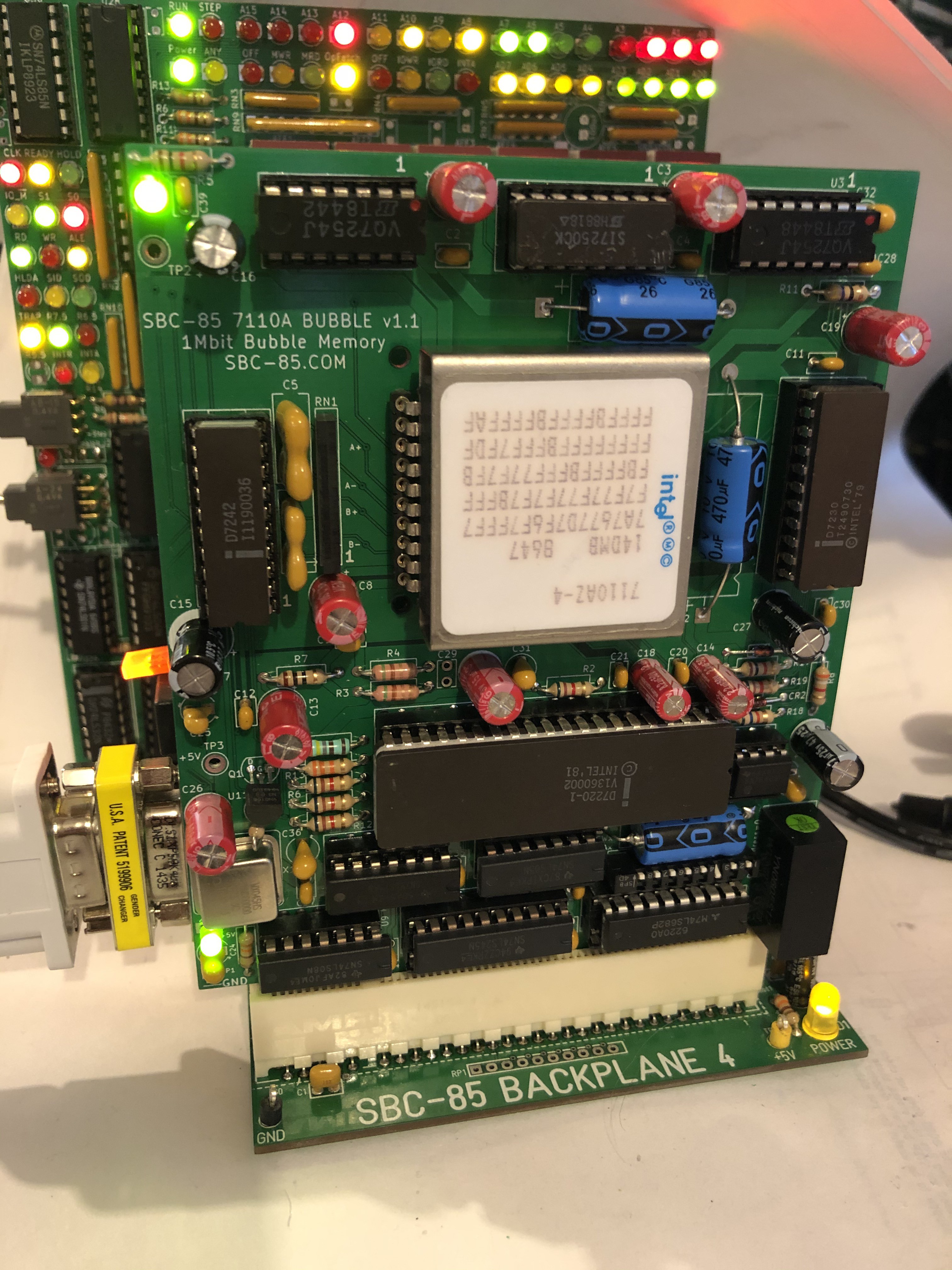
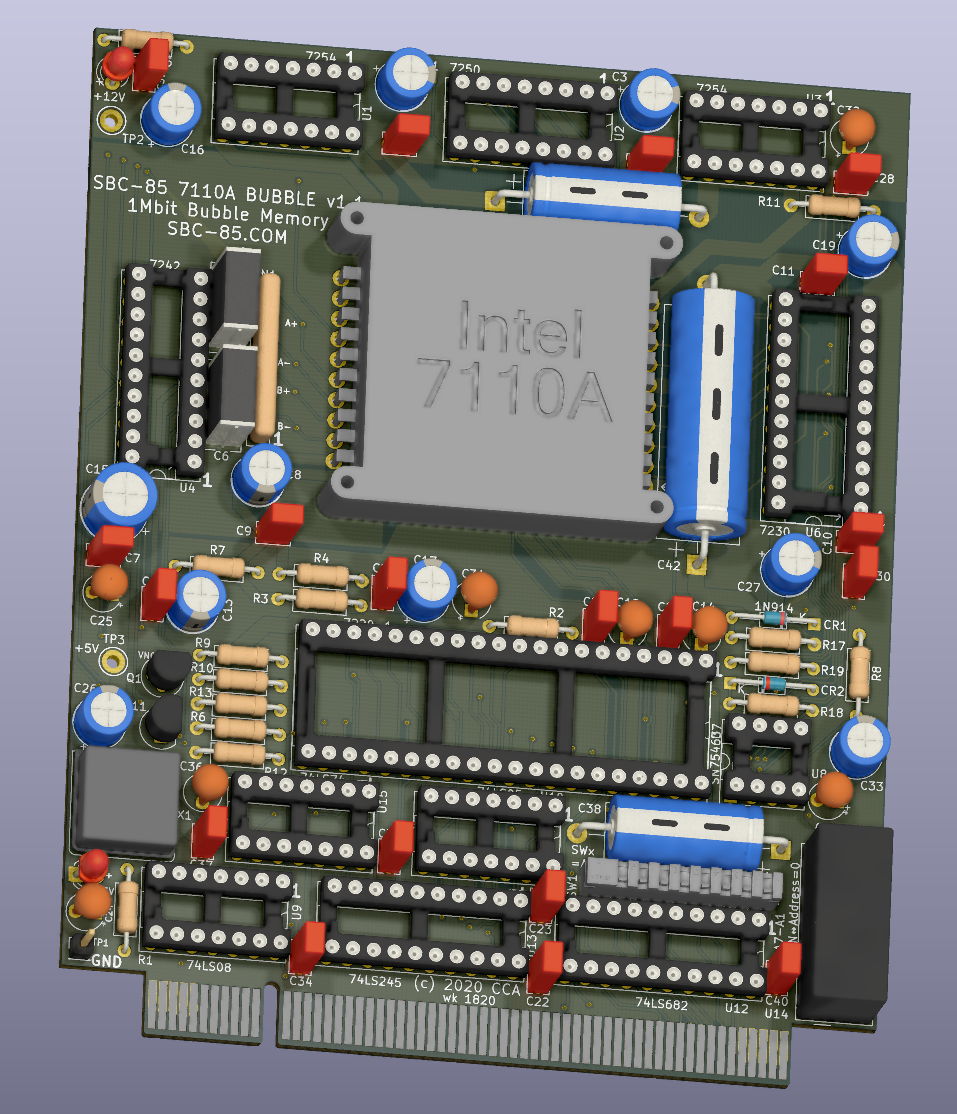
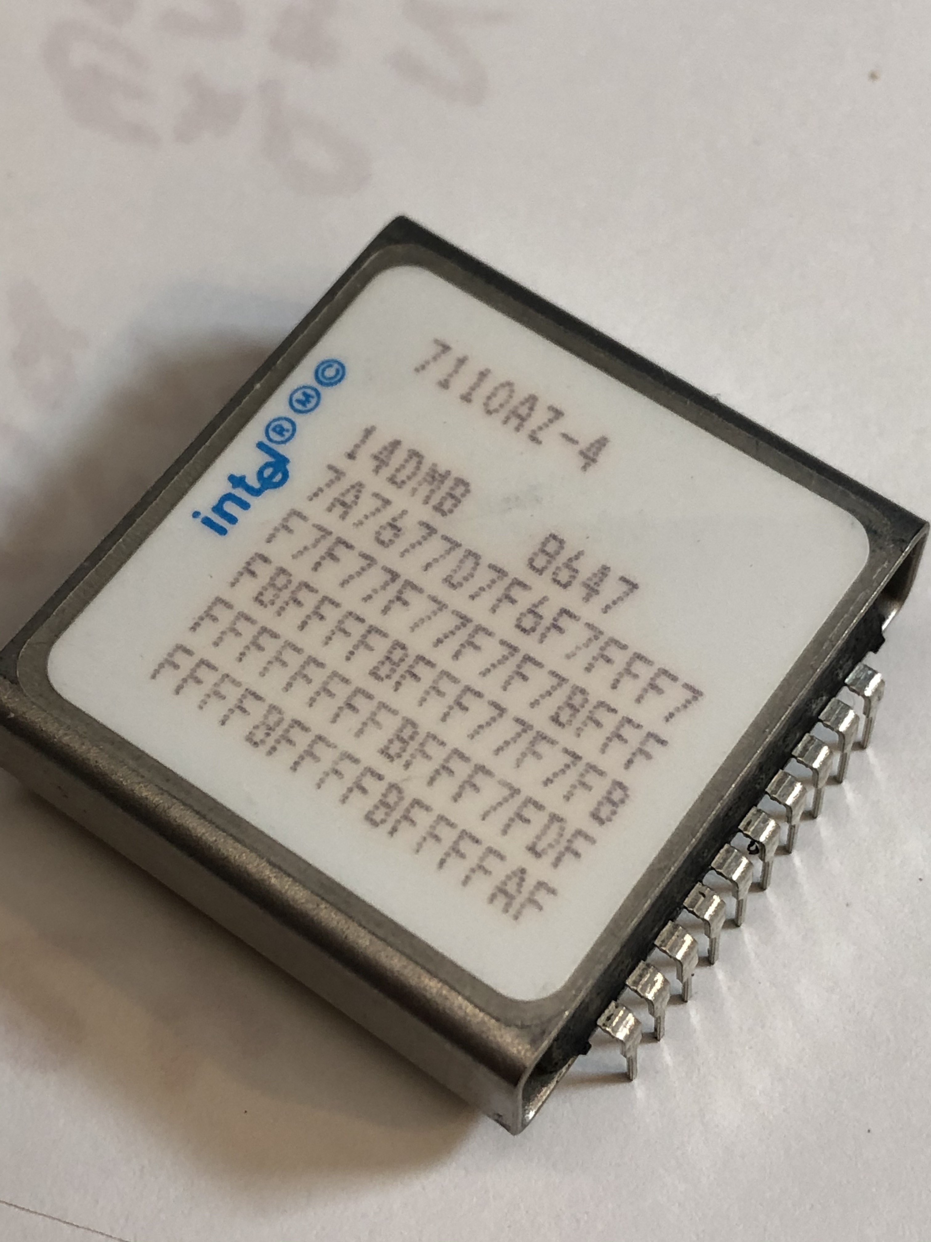
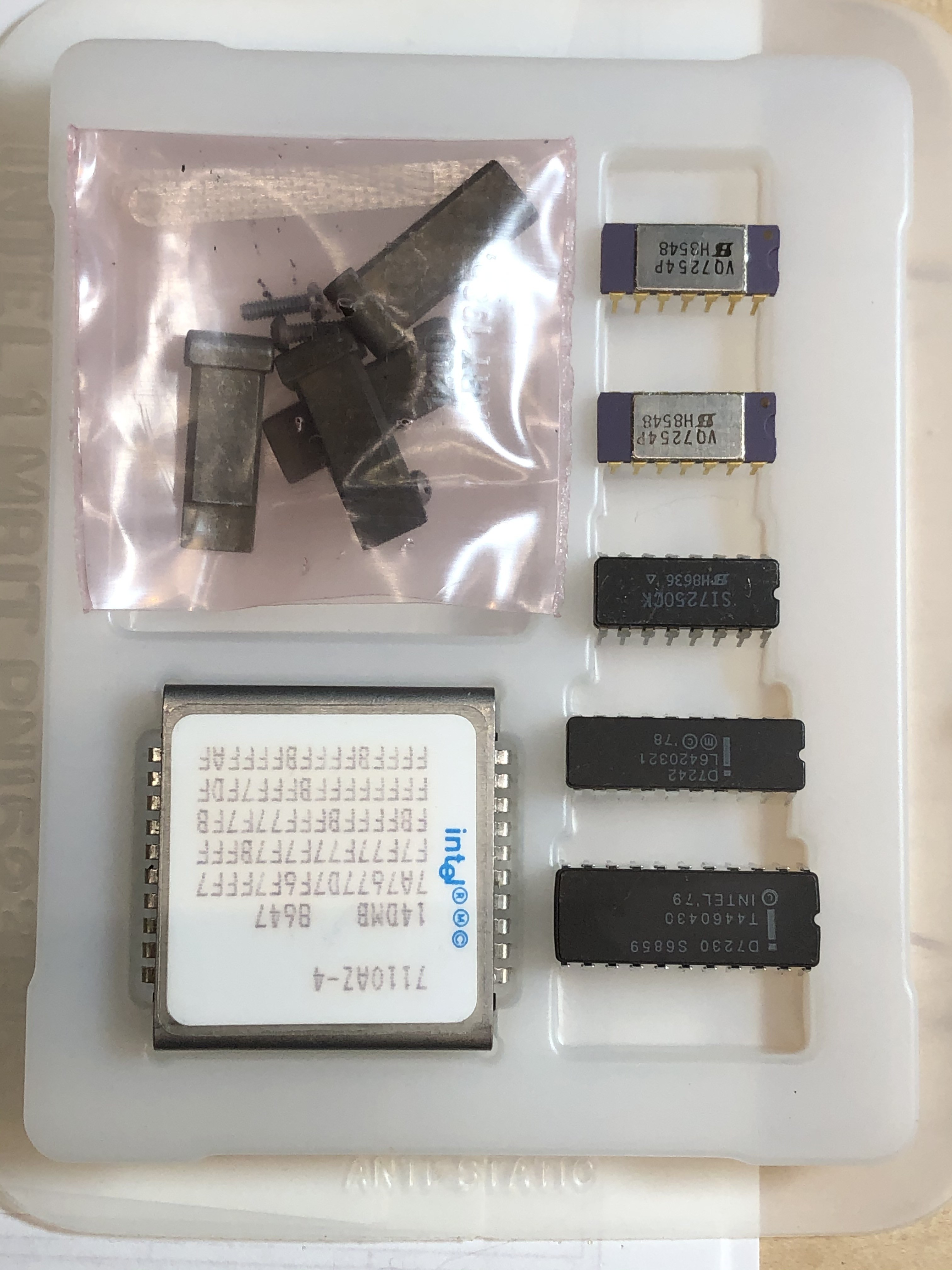
The photos are of the new board, a 7110A 20-pin 1Mbit bubble, and the BPK70A bubble kit.
-
Bubble Board Software - Where to go from here?
04/18/2020 at 21:12 • 0 commentsI am wondering, out loud, where to go next with the bubble board software for the SBC-85 1MBit bubble board. As it currently stands, I have subroutines that are called to initialize the board (called once upon power-up), write any number of bytes to the bubble, and read any number of bytes from the bubble.
The bubble device has 272 race tracks in each of two banks, and these are written-to and read-from essentially in parallel so a data 'page' has 68 bytes of information. This can be configured as 64 bytes with ECC or use the full 68 bytes raw (which is how I plan on using it). From a generic standpoint, accessing the bubble is done by specifying which page is desired (i.e., which of the 4K bubble locations on the race track the user wants), then the bubble controller simultaneously brings that particular bubble location on all 272 tracks to the read or write station, and then does a parallel read or write of all 68 bytes. Once the starting location is in place, the user can then sequentially read or write the specified number pages.
To use my write routine, the user first loads into memory buffers (1) the starting bubble page number, (2) the starting address of the source data, and (3) the number of bytes to be written. The routine is called which returns the bubble status byte when the operation is completed or times out. Since the bubble controller thinks in pages and not bytes, the number of bytes is divided by 68 to get the number of pages which is passed to the 7220. Also, since the 7220 controller will throw an error if a partial page is accessed, the routine fills out the rest of the page with filler during the transfer to the FIFO.
To use the read routine, the same parameters are passed, i.e., the starting bubble page, the destination memory address for the data, and the number of bytes to transfer. In this case the left over incoming bytes in the page are just sent to the bit bucket.
So obviously we can think of the bubble just like we would a disk with 68 byte sectors. When I started this board, my interest did not particularly lie in the software beyond the low level routines. However, to make the board usable, some sort of DOS will be required which is where I am now.
Right now I am leaning towards a 70's style chain topology which I have always favored for simple systems. I just have a table that includes a reference to the first page of a file, and then at the end of each of those pages there is a pointer to the next page. Reading was as simple as starting at the first page and then following the breadcrumbs from page to page. Overall memory formatting was accomplished with a "page utilization table" (PUT) that just had a bit set for each page used and reset for each free page. When writing to the memory, the first free page in the PUT was claimed as the starting page of the chain, and the file written one page at a time with the last two bytes pointing to the next free page subsequently claimed in the PUT. Hard to beat in terms of simplicity, easy to implement, easy to maintain, and no more subject to fragmentation than any other DOS.
So unless someone steps forward that is really into disk operating systems and wants to create something more exotic, this is going to be my path forward. But if anyone has any suggestions I am still in the pre-project thinking stage and willing to include any good idea.
regards
Craig
-
Making Bubbles, Chasing Bubbles, Reading Bubbles. Yea, this is fun.
04/18/2020 at 02:04 • 0 commentsWith everything seemingly working, confidence is at an all time high in the hardware and software and the possibility of successfully completing this project. After about four decades of wanting to build the 1 megabit bubble card for the SBC-85 system, it feels pretty darn good to see this on my bench and to read and write bubbles.
No rest for the wicked, so it is now time to return to the board layout so they can be on order while polishing the software. There were a few things that I have found wrong or I don't like on the PCB that I want to change:
- Somehow I must not have submitted a silkscreen layer because none of the component names are there.
- The footprint for the pinned version of the 7110 so I can use either the lead less with its carrier or the 10-pin.
- Add more bulk capacitance as it will fit to improve the voltage decay on the +5 and 12V
- Space the filter capacitors on the sense line further apart so the oversized silver mica will fit
- Move the top left electrolytic so it is easier to get a chip removal tool on the top left 7254 driver
I am pretty, pretty pleased.
-
Getting an underflow error on the 7220, anyone know what is going on?
04/16/2020 at 00:43 • 0 commentsWorking away on the software to make it easier to use the bubble board, and overall it is going well with completed routines to initialize the bubble, load parameters, read the boot loop, read the boot loop register, and write to the bubble. However, I am having trouble with an underflow error when reading the bubble
Using the bubble read command in poll mode, I can not figure out why my bubble memory board is letting me read past the initial FIFO load. I can write to the bubble and the 7220 FIFO status flag seems to be working fine (or possibly it is writing faster than I am filling). I can also read the boot loop and the boot loop register but those fit in the FIFO so the problem does not show up. The problem only seems to crop up when reading a page from the bubble and then only past the first FIFO load. Operating in polling mode with enable byte of 0x00, and the first FIFO load can be read without problems. Up to about byte 24, the status stays 81H as expected but a few bytes later the data turns to 00H as if reading past the FIFO but the status byte is still 81H. a few more byte reads and the status byte flips directly to 91H but the FIFO ready flag never goes to low as expected. After the full page read, the busy goes low and the status byte is now 30H so it is indicating a failed opcode and timing error as expected for a underflow error if reading past the FIFO load.
This has tied me up for most of the day. Anyone familiar enough to with the intel 7110 and 7220 bubble system to be able to give advice?4-18-20
UPDATE - Much Ado About Nothing:
It took me another day to track this down but I am happy to report that everything now seems to be working and I can now reliably use the bubble board!
After starting to dig into the hardware, looking at the serial communication between the 7220 and the 7242 and many scope traces later, it turns out that the problem was not hardware related but there was simply an issue in my initialization routine. Mostly by accident I discovered that if I switched to the low-level command mode (which sends commands directly to the 7220 bubble interface and the 7242 preformatter) and sent the 11H code to reinitialize the 7220, then bubble reads would start working for the higher level commands in the finished code. I did not catch this in the quick-and-dirty code because it was limited to single FIFO reads out of "convenience". After that discovery, it was just a matter of tracking down the bug in the new code. In both cases I was setting up the parametric registers properly but in the finished code (that has error checking and reporting) I messed up a bit-mask for the status read and as a result the code was inadvertently skipping over a key step of the initialization. The funny thing is that this bug would only show up in the bubble read and then only when going past the first page of the FIFO. That is sort of an odd time for an initialization bug to show up and I became convinced that the 7110 was somehow having trouble rotating or duplicating onto the output track. So all is well that ends well and I learned a *lot* more about these chips in the last two days !!
Thanks
Craig -
"While it is unlikely that the 7110 can be seriously damaged....." - Intel
04/10/2020 at 20:17 • 0 commentsMore reassuring words have never been spoken. To quote the Intel Application Note AP-119
"While it is unlikely that the 7110 can be seriously damaged, it is possible for the seeds and bootloop ... to be lost."
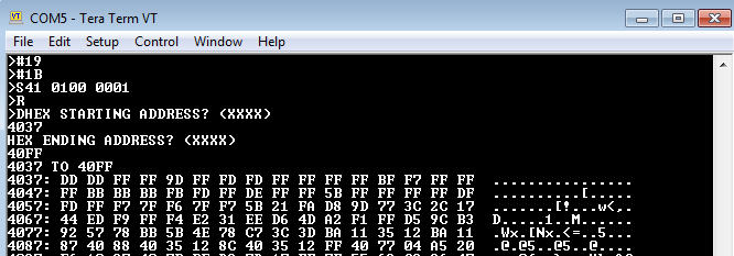
Since I can re-seed and re-enter the bootloop if necessary, given this morale booster (and after thoroughly checking all of the waveforms driving the 7110) I went ahead and populated the bubble chip itself. Right out of the gate I did a register configuration, then abort with the "9" command and a read of the bootloop using the "B" command. Then saved the 7220 FIFO to the SBC-85 RAM and dumped ....
... then anxiously compared the dump to the bootloop printed on the device.
Whoop Whoop Whoop.
What we have here is a very, very, very good step.
Obviously at this point I am still manually hacking my way through all of the commands in pretty raw form. Now back to writing more software so it is easier to read and write to the bubble.
Once the next level of software is written, I will be able to read and write to the bubble itself. The first check is to make sure the seed bubble is OK, but since the bootloop was intact there is no reason to suspect that this module needs to be reseeded.
-
Fingerburner tip. The 7254 uses no protection
04/10/2020 at 16:21 • 0 commentsTo learn more about the system and what errors it will detect and report, I am looking at waveforms and playing with the system under various configurations.
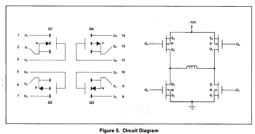
Not completely unrelated, the simplified diagram for the Intel 7254 drive transistor bridges that run the X and Y coils in the 7110 bubble looks like this---
If you ever wondered to yourself "Does the 7254 have pull downs on the gates that keep the FETs from floating ON which would result in the chip shorting itself from +12V to ground and therefore burning itself up?" Well, the answer is no.
Note to self--- The 7254 has nothing to keep the gates from floating on. Never run the 7254 without the pre-coil drive 7250 in place. I don't know if this set still works, but I doubt they are still a matched pair as when new and now the tip of my finger smells like a combination of melting plastic and burnt flesh. I am glad they were a recovered set and not my good chips.
-
Support Chips Installed, Preliminary Checks Passed
04/10/2020 at 03:36 • 0 commentsI only had a couple of hours to work on this today, so I make a relatively small amount but very critical progress. I am always a bit nervous with 40 year old chips, so after double checking the power rails, the 7220 bubble memory controller chip was installed and the system powered up. As a first test, base communication with the 7220 controller was confirmed with simple commands like read status, write data block to FIFO, confirm data integrity, etc. Seemingly minor progress, but a significant step.
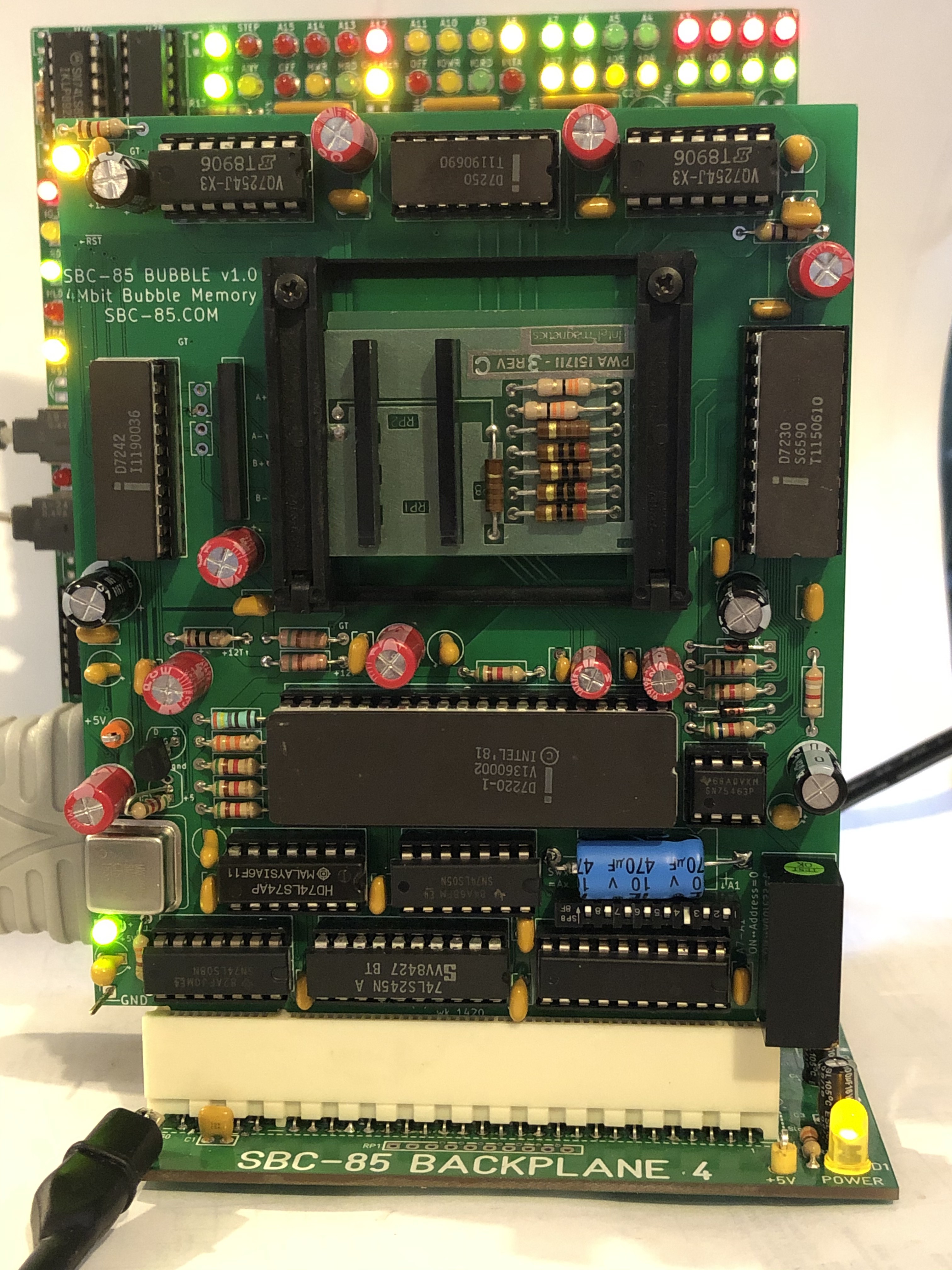
One by one the remaining bubble support chips were installed, the board powered up, and temperature tested. All seems OK so proceeded to resistance tests with the dummy module. As seen in the photograph below, the dummy module is a PCB inserted in place of the 7110 bubble module.
![]()
The dummy module resistances and footprint match the 7110 bubble module, so while it will cause all sorts of errors, it provides the correct loading for all the drivers. After installed and its resistances double checked insitu, the module was installed and powered up.
So far all looks good so next time it is on to driving waveform tests and finally trying the 7110 bubble module itself.
Magnetic Bubble Memory Makes a Comeback
An Old Attraction to Magnetic Bubble Memory leads to a 1Mbit Board for the SBC-85, 8085 based single board computer
 Craig
Craig