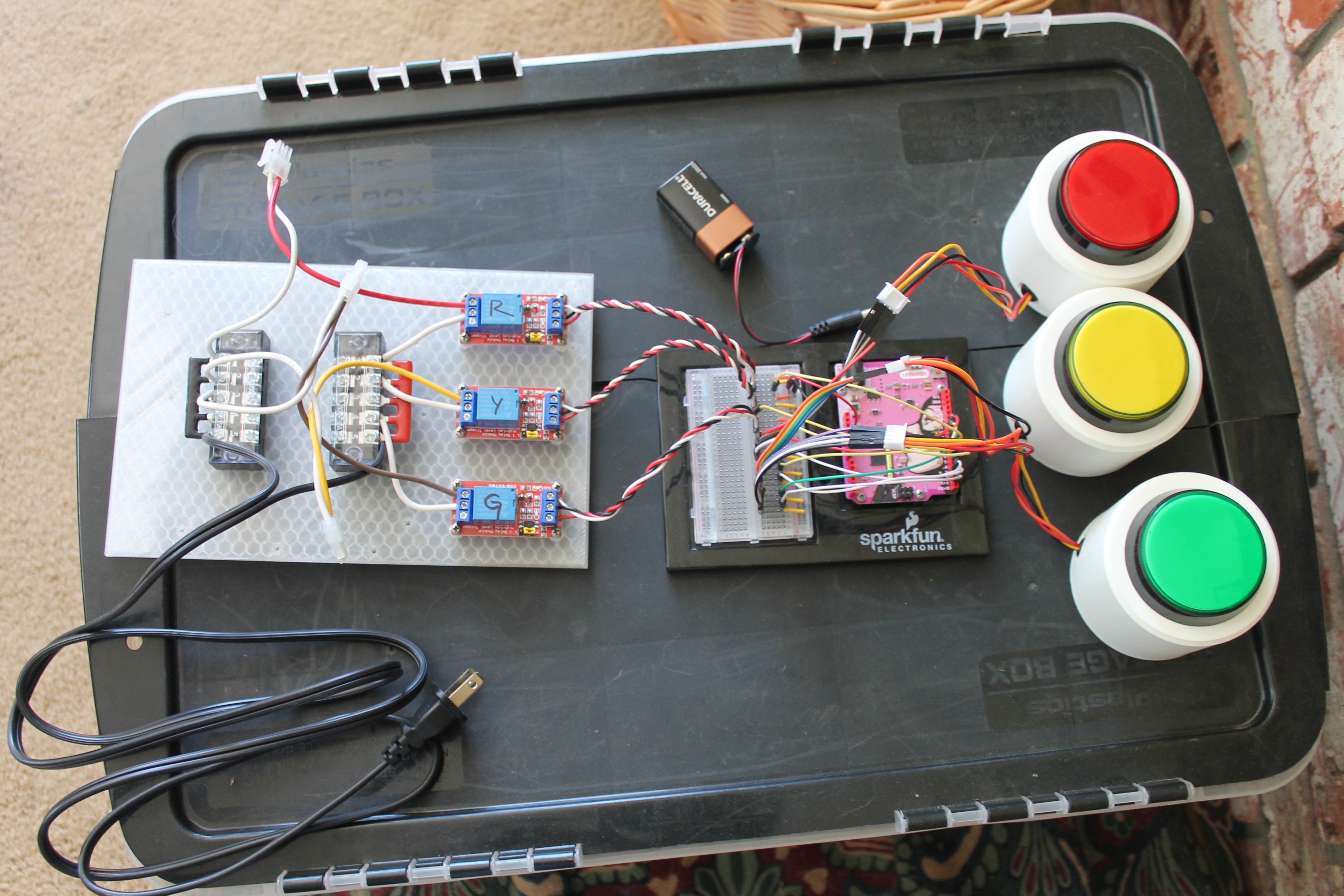
We used an arduino to control the traffic lights via relay modules because we wanted the flexibility to change the interaction of the buttons with the traffic lights and for the simplicity of programming. In total 9 pins were used, 3 for the switch inputs, 3 for the switch lights and 3 for the relay modules. Relay modules were used because the traffic lights operate off of 120 VAC. We also made a small traffic light simulator using a perfboard and 3 LEDs this way we wouldn't need to hook up to the giant traffic lights every time we wanted to test the code.

We already had a Leonardo microcontroller and breadboard mounted on a base plate. We then took the 3 relay modules and the 2 terminal blocks and mounted those onto a larger 3D printed scrap base plate. Following the schematic previously drawn up we wired together all of the components. To connect the lights to the relay modules I attached 3 two pin molex connectors to the output, 1 for each color. Then attached the mating connectors to the traffic lights. We 3D printed custom housing for the large lighted buttons.
 Robyn W
Discussions
Become a Hackaday.io Member
Create an account to leave a comment. Already have an account? Log In.