 danjovic
Nothing more appropriate to this third release than a firmware that can handle 3 controllers:
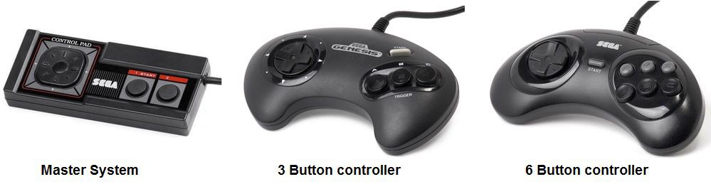
The firmware can work with either controller and will report buttons in the following sequence:
| Mapped Button | Genesis 6 button | Genesis 3 button | Master System |
|---|---|---|---|
| 1 | A | A | 1 |
| 2 | B | B | 2 |
| 3 | C | C | |
| 4 | X | ||
| 5 | Y | ||
| 6 | Z | ||
| 7 | START | START | |
| 8 | MODE |
Besides the Arduino Micro, only one component is required: A DB-9 male connector:
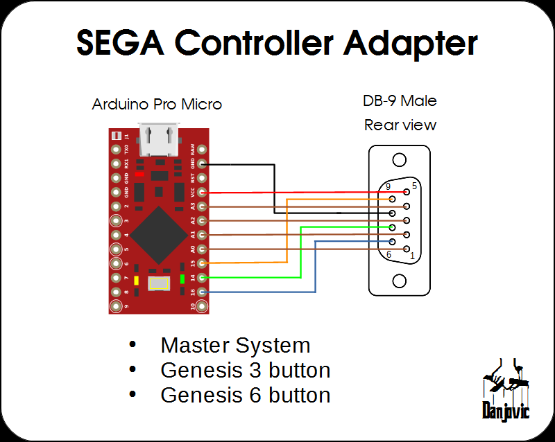
The prototype was assembled on a proto-board:

Identifying the controllers
The basic controller is the Master system controller that uses 6 rubber keys to deliver a D-Pad and a couple of buttons. Nothing unusual to notice here except that most of the lines of the DB-9 controller are occupied, as the Master System joystick port have a +5V and a GND line, adding up to a total of 8 out of 9 lines being used.
The Sega Genesis used the same DB-9 connector for the joystick port to maintain compatibility with the former controllers the new controller have more buttons than available lines (D-Pad plus 4 buttons: A, B, C and START). The solution adopted by SEGA was to use the remaining line to command a Multiplexer thus providing the twice times the number of lines, but that was not so easy as one problem left: How do the games would differentiate which button is which when a Master system controller was connected? Again the solution was simple. When a Genesis controller is connected and the selection line is unactive (low) then both Left and Right directions would be active at the same time, and that is a condition than would never occur on a Master System controller given the mechanical design of the D-Pad cross.
Pin:  9  6  4  3  2  1
Sel=0 ST A  0  0  DW UP
Sel=1 C  B  RG LF DW UP
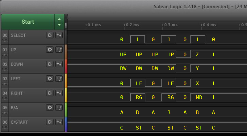
When the 6 button controller was introduced a similar problem showed up and this time the solution adopted was very peculiar. Another Mux was added inside the controller for the extra buttons and the control of such Mux is triggered by a counter that in turn is activated by the "Select" Line. After the third edge the extra mux is activated and the buttons X, Y, Z and MODE are present on the data lines. But one problem left (again). How to synchronize the game code with the pulse count? Simply counting the pulses issue is out of question since the controller can be inserted and removed while the game is running.
The solution for the six button controller used two mechanisms:
The first is to generate another invalid pattern, this time with all directionals activated at the same time right before the extra buttons ( X, Y, Z, MODE) are ready to be read. Additionally, all the directionals are deactivated on the next edge after the extra buttons are read so the game can differentiate between the "all directionals activated" from "all extra buttons activated".
Pin:   9  6  4  3  2  1
Sel=0  ST A  0  0  DW UP
Sel=1  C  B  RG LF DW UP
Sel=0  ST A  0  0  DW UP
Sel=1  C  B  RG LF DW UP
Sel=0  ST A  0  0  0  0  -> Directionals LOW right before extra buttons
Sel=1  1  1  MD X  Y  Z     3rd rising edge
Sel=0  ST A  1  1  1  1  -> Directionals HIGH right after the extra buttons
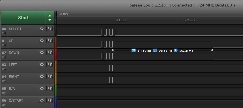
The second mechanism is a timeout. It the Select line do not change state again within ~1.5ms then the internal counter is reset.

The code performs a series of samples and checks the state of the unique conditions to identify whether the controller is a 3 button or a 6 button controller. If neither one is identified the code assumes that the controller is a Master System (or unknown)
uint8_t SEGAscan(void) {
  uint8_t sample[7];
  uint8_t type;
  combinedButtons = 0;

  sample[0] = readController();   //  ST A  0  0  DW UP

  digitalWrite(genesisSelect,HIGH);
  sample[1] = readController();   //  C  B  RG LF DW UP

  digitalWrite(genesisSelect,LOW);
  sample[2] = readController();   //  ST A  0  0  DW UP

  digitalWrite(genesisSelect,HIGH);
  sample[3] = readController();  C  B  RG LF DW UP

  digitalWrite(genesisSelect,LOW);   //
  sample[4] = readController();  ST A  0  0  0  0

  digitalWrite(genesisSelect,HIGH);
  sample[5] =  readController();  //  1  1  MD X  Y  Z

  digitalWrite(genesisSelect,LOW);
  sample[6] = readController();   //  ST A  1  1  1  1

  // check for 3 or 6 buttons
  if ( ((sample[4] & 0x03) == 0) && ((sample[6] & 0x0f)==0x0f) ) {
     type = _6Button;
  } else if  ( (sample[6] & 0x0c) == 0)  {
     type = _3Button;
  } else
     type = _unKnown;
...
...
}
The rest of the code uses sampled data to form a 16 bit word with the state of all buttons, as applicable to the type of controller.
  // now populate combinedButtons variable accordingly       // 15 14 13 12 11 10 9  8  7  6  5  4  3  2  1  0
  combinedButtons = (uint16_t)sample[1];                     // 0  0  0  0  0  0  0  0  0  0  C  B  RG LF DW UP
  combinedButtons |= ((uint16_t)(sample[0]<<2)) & 0xc0;      // 0  0  0  0  0  0  0  0  ST A  C  B  RG LF DW UP
  combinedButtons |= ((uint16_t)(sample[5]<<8)) & 0xf00;     // 0  0  0  0  MD X  Y  Z  ST A  C  B  RG LF DW UP
...
  // invert bits. Make '1' the active state
  combinedButtons = ~combinedButtons;
  switch (type) {
    case _6Button:
      combinedButtons &= 0x0fff;
      break;
    case _3Button:
      combinedButtons &= 0x00ff;
    default:
      combinedButtons &= 0x003f;
    }
And that concludes the third release.
Discussions
Become a Hackaday.io Member
Create an account to leave a comment. Already have an account? Log In.