 Phil Malone
Once I received my new HOVER-1 ULTRA, and discovered that it had two separate motor controller boards, I knew I had some research ahead of me.
To cut a long story short, I found two great projects that could help me with code.
The first source was a Software repo by Florian, a German Software and Hardware developer.
https://github.com/flo199213/Hoverboard-Firmware-Hack-Gen2
This appears to be the first code repository that deals with the Dual controller code.
An interesting adaption of Florian's code was made by Gaucho, in Rome.
https://github.com/gaucho1978/CHEAP-LAWNMOWER-ROBOT-FROM-HOVERBOARD
By combining information from both of these projects, I was able to establish a starting point for my own code. I actually used Gaucho's code to verify that I could succesfuly build and deploy working code, but in the end I used Florians code as the basis for my own project.
The Florian Repo came with the following Flashing instructions
-------------------------------------------
The firmware is built with Keil (free up to 32KByte). To build the firmware, open the Keil project file which is includes in repository. Right to the STM32, there is a debugging header with GND, 3V3, SWDIO and SWCLK. Connect GND, SWDIO and SWCLK to your SWD programmer, like the ST-Link found on many STM devboards.
- If you never flashed your mainboard before, the controller is locked. To unlock the flash, use STM32 ST-LINK Utility or openOCD.
- To flash the STM32, use the STM32 ST-LINK Utility as well, ST-Flash utility or Keil by itself.
- Hold the powerbutton while flashing the firmware, as the controller releases the power latch and switches itself off during flashing
--------------------------------------------
So I ordered the ST-LINK interface from AdaFruit.com, and downloaded the Keil software from https://www.keil.com/demo/eval/arm.htm and the ST-LINK Utility from https://www.st.com/en/development-tools/stsw-link004.html
I mounted header pins for programming and serial debugging, and stared down the road of figuring out what the various elements did.
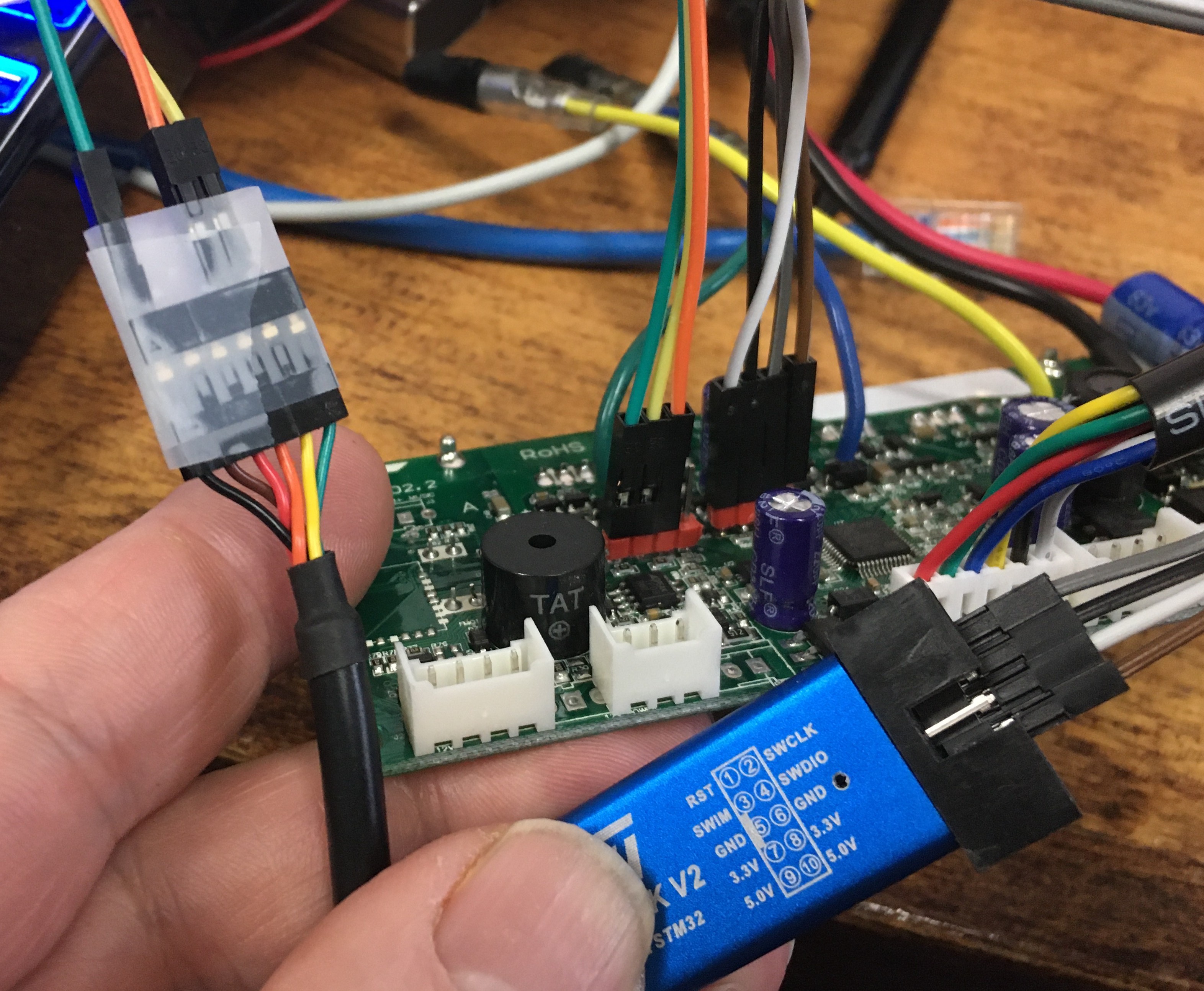
The following picture shows the two cables that I assembled for programming and debugging. The ST-LINK module was connected to the programming header by 4 wires. This provided the communications AND power for the processor. Note: the processor runs on 3.3V (not 5V). Also shown is the serial debugger cable that uses a USB-TTL Serial interface like this one. Note that the power from the debugger cable is not used, and the interface is 3.3-5v compatible.
Discussions
Become a Hackaday.io Member
Create an account to leave a comment. Already have an account? Log In.