Most makers working with the ESP32 can easily accomplish their goals by using the ESP-IDF integration with the Arduino IDE. With my background in hardware and low-level software, I wanted to learn a bit more about the ESP32 and went with the ESP IDF (coupled with Visual Studio Code. (The blog post linked from the Project page discusses some of the work I had to do to get it working in the somewhat exotic environment I work in on a daily basis.)
This meant I was exposed to FreeRTOS resource management and multitasking, and I had some fun.
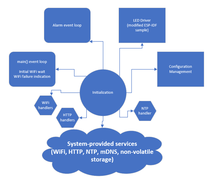
The IDF sample project starts with a 'main' function that runs in its own FreeRTOS task (thread). As peripherals are initialized and started, relevant tasks, events, and ISRs are set up. The programmer is then left to build on top of this.
Overall, the code is split into:
- Color Space APIs
- LED patterns and colors
- Configuration management
- HTTP handlers
- Alarm+Sleep state machine
I ended up with two event loops of my own: a vestigial one in the 'main' task that keeps the WiFi up and an alarm loop that tracks time and listens for configuration events.

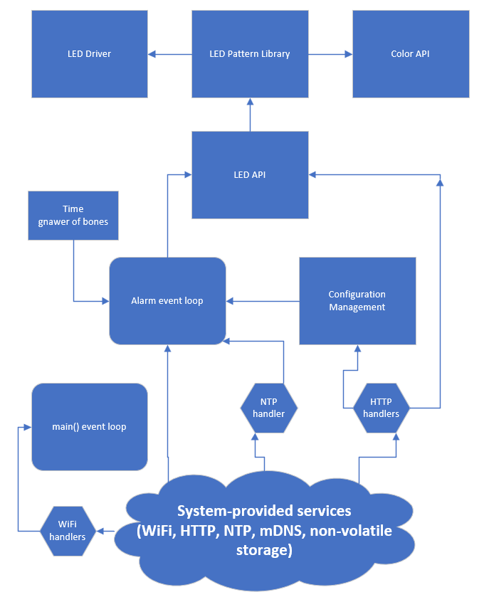
Here's a look at how these parts talk to each other, whether by function calls or events, during normal operation:

The ESP-IDF services all expose either a direct call interface--where a function is called to perform a given task--or a callback-based asynchronous interface. For my own services (the LEDs and the configuration engine), I crafted rough approximations of the same. The HTTP handler calls into the config engine which then calls a static callback to inform interested subsystems that they should re-read their configuration. The LED service has a single exposed function for running LED patterns, which internally uses a mutex to ensure only one command is processed at a time. The underlying code makes extensive use of my color space APIs to convert various conceptual concepts, like 'green' and '3100K', into linear RGB which then gets gamma-corrected by the LED driver itself.
The color APIs all rely on only function arguments and locals, making them state-free and so lock-free.
The alarm event loop is not direct-call or callback-based. Instead, it uses events and event wait timeouts to receive things like HTTP events (snooze, stop) and time changes.
Time is tracked by the onboard RTC and periodically updated via NTP. As an alarm clock on mains power, no attempt was made at power management.
Nothing makes code easier to maintain than good comments (except maybe good docs in addition to good comments :). Knowing I would probably take quite some time away from this project and seeing that I was learning a lot as I went, I put as much documentation as I could in the code.
 Jon Kunkee
Discussions
Become a Hackaday.io Member
Create an account to leave a comment. Already have an account? Log In.