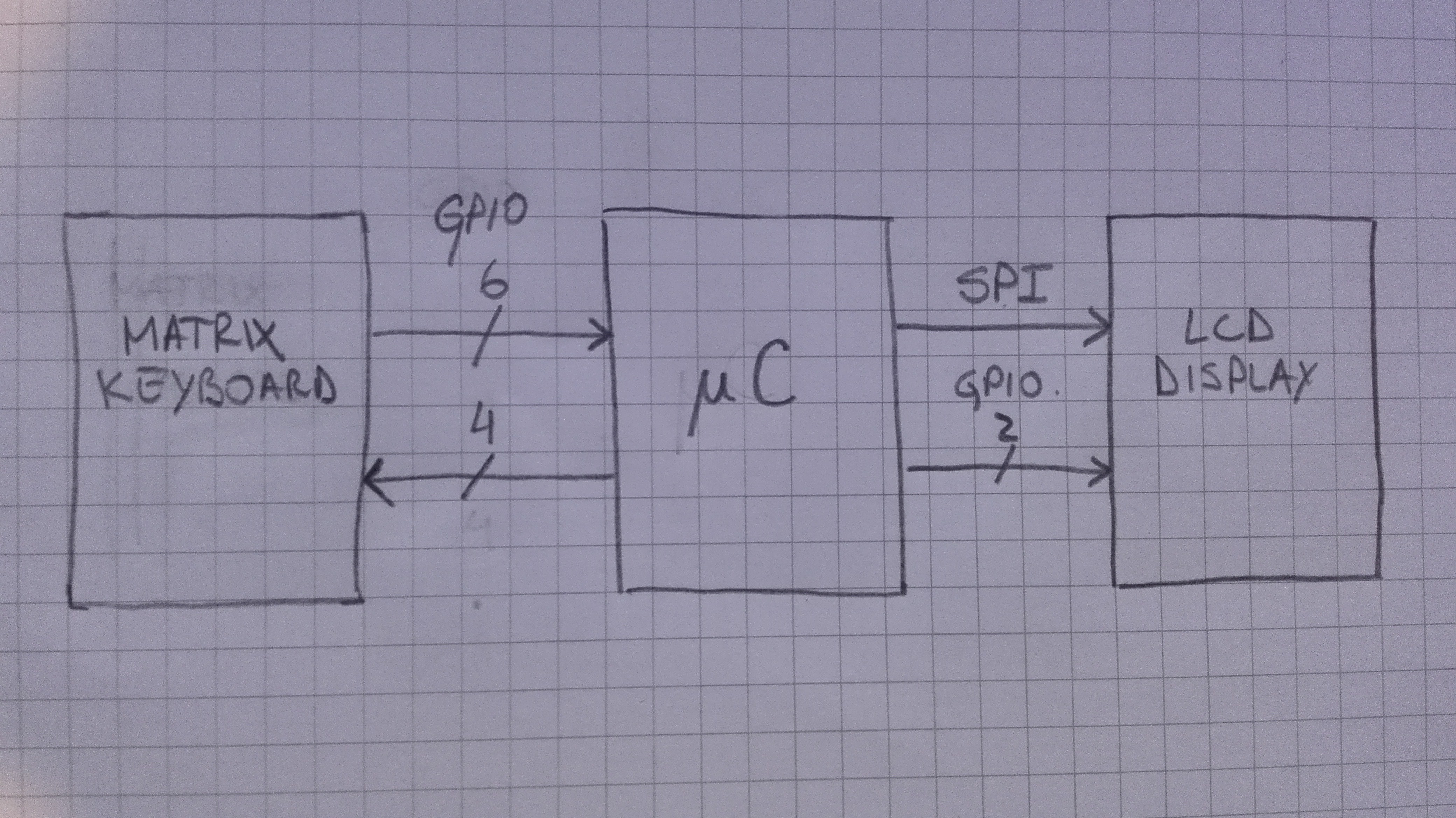
After taking care of the power lines, decoupling capacitor and power supply related things, the main components are connected as shown:

For the matrix keyboard only 10 GPIO were used. Four are used for scanning and six for reading. The entire scan sequence was automated using the DMA capabilities of the micro controller. The only task done by software is the decoding of the input data.
For the LCD the SPI hardware was used for the communication, and two additional GPIO were for data/command and reset. Like the keyboard, the transfer of graphics data through SPI were automated using DMA. With this the programmer can write all he need in the dedicated graphics memory at any moment and the DMA is going to transfer it to the LCD. At certain point, this is like a linux frame buffer.
Discussions
Become a Hackaday.io Member
Create an account to leave a comment. Already have an account? Log In.