See here for details.
Fixing Up the Monoprice Select Mini
The Monoprice Select Mini (MPSM) was a great printer at a great price point. But it needs a few fixes.
The Monoprice Select Mini (MPSM) was a great printer at a great price point. But it needs a few fixes.
To make the experience fit your profile, pick a username and tell us what interests you.
We found and based on your interests.
See here for details.
BlowerFanMount.zipAll STLs Required for the 30mm Blower Fan Mountx-zip-compressed - 110.26 kB - 05/07/2020 at 02:51 |
|
|
Z-axis-brace.zipAll the STLs required to print the Z-axis bracex-zip-compressed - 1.76 MB - 04/17/2020 at 15:39 |
|
|
FanShroud.zipA fan shroud with space for an integrated circuit board to control a fan and LEDs. Designed for use with this fan mount: https://www.thingiverse.com/thing:1848402x-zip-compressed - 335.58 kB - 04/17/2020 at 15:39 |
|
|
LED-Gantry-Upgrade-Files.zipClips and an end bracket to install a gantry LED strip and switch.x-zip-compressed - 547.89 kB - 04/17/2020 at 15:39 |
|
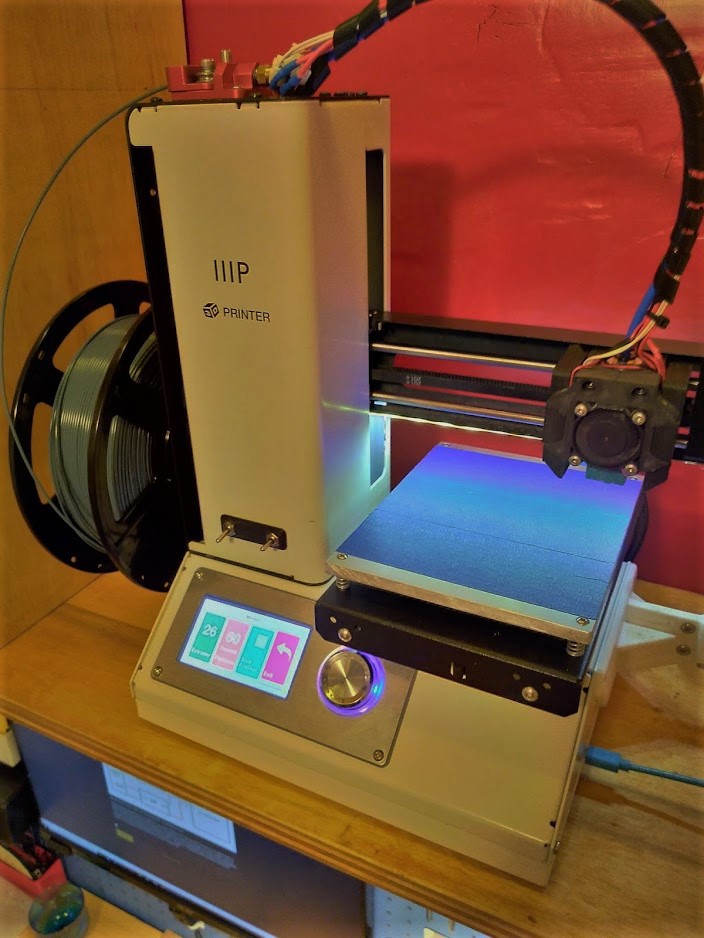
Out of the box one of my biggest issues with the MPSM was the heated bed. After mild use, it quickly warped, was unable to warm up, and had uneven heat distribution. One of the quick fixes that many people do, including myself is to install a glass sheet on top of the heated bed. This works, but I found myself desiring a cleaner solution. I also still found that I needed to occasionally adjust the bed leveling, something that shouldn’t really be necessary on a printer bed this small.
Back in February I ordered all of the parts to build a brand new heated bed for my printer that solved all of the above issues. For this project I needed an SSR, 1/4” aluminum plate, and a 110mm2 12v heating pad. Zipties and wire are useful too. While I waited for parts to mail from China, I started by cutting the aluminum sheet I got from a local metal supplier. I debated using MIC6 tool steel, but I decided it wasn’t needed for such a small bed. I cut it to size using a tablesaw (yes it works if a little rough) and filed down the edges. I finished with a bit of sandpaper and cooking oil to bring out a bit of shine.
Next up I cut the holes using my CNC machine. Using a drill press would work fine for this portion as well. The corner to corner measurements I had came out to about 118mm x 152mm and mount perfectly on the machine as is. You could easily expand the bed using this method, but I’m ok with a smaller printer.
When the parts finally arrived, I started by drilling holes in the back of the frame. I would have liked to have installed the SSR internally, but I already have an internal meanwell 12v power supply so there isn’t any room left! I drilled holes for the control wires coming from the printers main board and additional wires to attach zipties to for strain relief. I mounted the SSR on the back of the frame with some M3x8 bolts and wired the the heated bed as seen below. You can see them all in the included picture.
After putting everything back together, I am quite pleased with the results! The aluminum plate does a great job distributing the heat, and there is no evidence of bed warping after a couple dozen hours of use, I haven’t had to adjust the leveling once! Additionally, the heated bed has an easy time hitting 60°C and can with a bit of patience get as high as 80°C. I suspect If I installed some insulation along the bottom of the bed, there would be no issues whatsoever.
WARNING: This design will remove 10mm from your x axis, be sure to update your slicer profiles!
A long time ago in an apartment far away I installed US Water Rockets E3DV6 Carriage on the MPSM. I quite like the carriage. The integrated belt tensioner was great and the design was sleek looking while easy to print. Since that time I built a Voron 2.1 printer and the MPSM has been sitting on my shelf since its completion. Recently I decided to focus some time on making the MPSM a rock solid platform that produced reliable prints. I was never a huge fan of the 30mm clip on fan that was designed for the front of the carriage. I liked the integrated LEDs, but I really wanted better visibility at the nozzle than what they could offer. Additionally, the single 30mm fan didn't move a whole lot of air over the part. I attempted several other designs and I wasn't a huge "fan" of any of them. The designs that seemed to move a fair amount of air seemed a little janky to me, so I decided to design my own.
There was one compromise that I needed to make. To mount two 30mm blower fans onto the printer, I needed to give up 10mm of the x axis. Again, I have another printer at this point, so 10mm wasn't a huge deal to me, compared to superior and compact cooling. If you absolutely NEED the full 120mm this is not the design for you, although you could probably just cut the fan on the left side off.
To install this mod, you will need the following in addition to what is already installed on the printer:
4x M2x10 Socket Head Screws
2x 30mm 12v blower fans
2x M3x25 Socket Head Screws
4x M3x15 Flat Head Screws (Self tapping if you have them!)
1x Silicone Sock for Heater Block (If you don't install this, your printer won't heat up)
1x 30mm fan shroud (optional)
Most of these items can be easily found on aliexpress.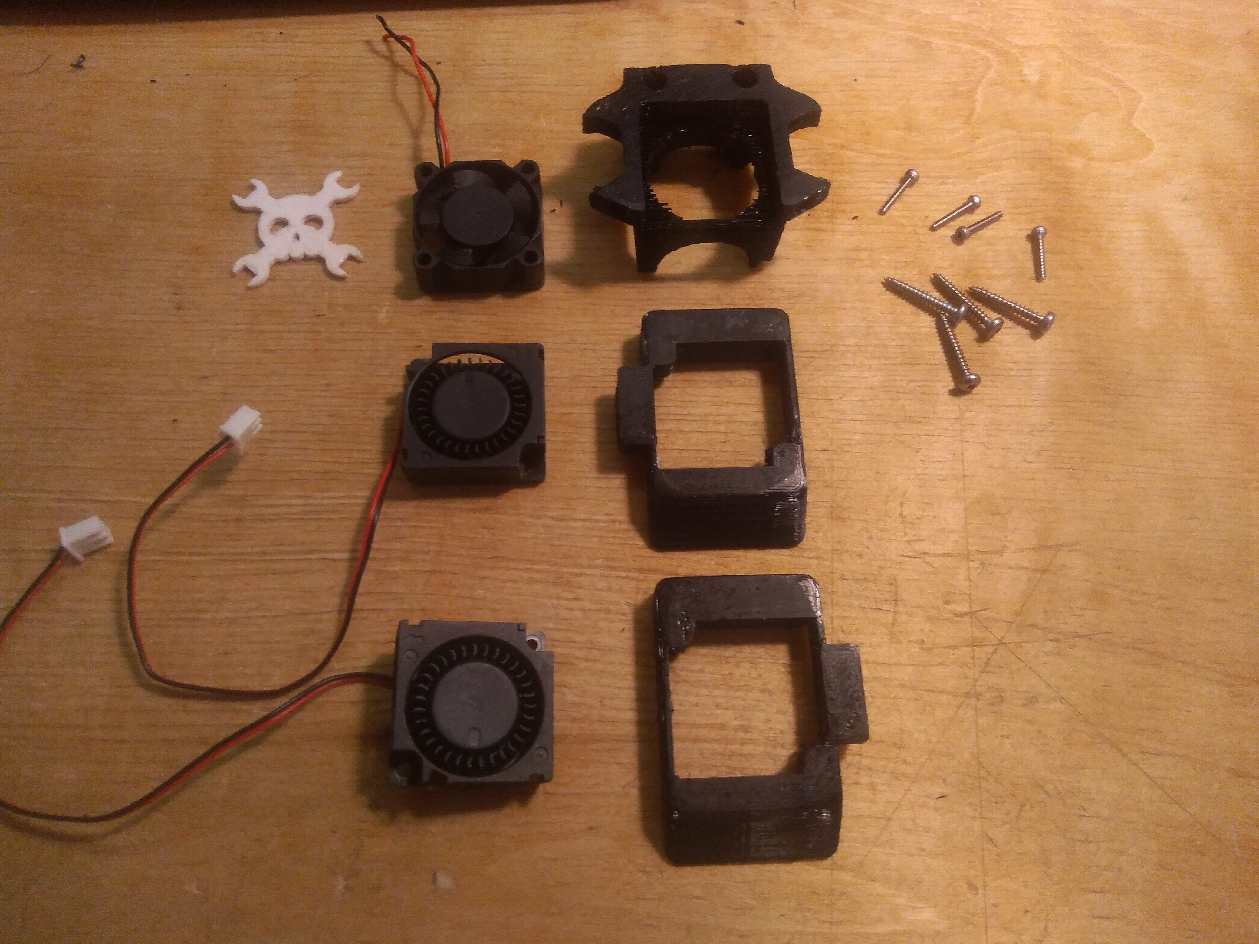
Start by printing off the files that I designed. PETG should work and is fairly printable on the MPSM. I used some carbon fiber PETG I hold on to for special occasions. You will need to cut away a thin layer of bridging material from the carriage mount using an knife or flush cutters. It may also be helpful to drill out the holes as well.
Install the blower fans into the side mounts. I found I didn't need to screw them in place and a press fit worked fine, but if you need to there is space to use some M2 screws to hold them in place. You will see that on one side I have designed a small channel that the cord from the fan can be run up the side of the mount. Once the fans have been pressed into place, you can then screw them on to the carriage mount using the 4x M2x10 screws. The recess holes are installed in the top and bottom of the mount. You can then install the 30mm fan on the front of the mount. Assembled the unit will look like this:
You can now install it on the carriage using M3 screws You need slightly longer screws than the ones on the original water rockets design so that is why I have included 2x M3x25 screws in the instructions. The fans can be wired directly to the 12v input into the machine. I've installed a small switch on the front of the machine that I use to control them. Unfortunately the MPSM doesn't seem to have the ability to vary fan speed, so its either all or nothing!
Here's what the finished unit looks like (wiring was cleaned up later!):
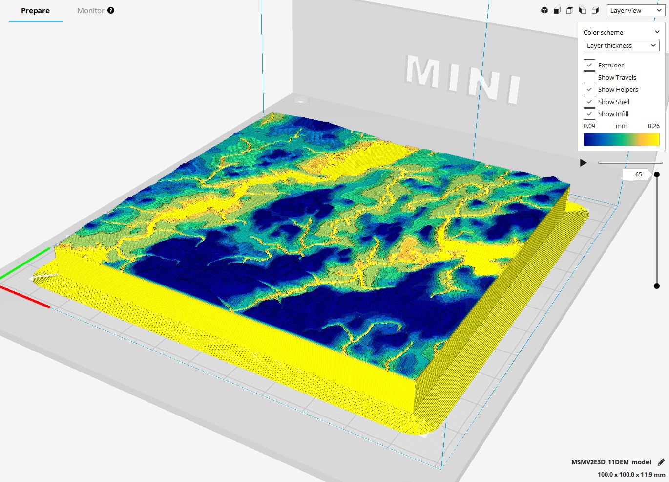
Recently I started printing 3d topographies as an educational tool. They are relatively flat for the majority of the print, but when it comes to the surface, having thicker layer heights left much to be desired. Due to the large volume being printed, setting a smaller layer heights sent printing times through the roof. I needed a better solution. Enter adaptive layer heights.
Setting the layer height to 0.0875mm creates a detailed surface, but dramatically increases print time.
Variable or adaptive layer heights can increase detail being printed on sloped surfaces relative to the XYZ axis on your printer, while layers parallel to any axis can be printed thicker since it is not as imperative for surface detail. The unique problem with the monoprice select mini is that the stepper motor used to drive the Z axis has an unusual property that sets the minimum resolution to a nice even 0.04375mm. In order to ensure top quality prints while reducing print time, we must first understand each of the settings.
To use adaptive layer heights, you must enable it under Cura’s experimental options.
The maximum variation is the maximum distance that layer height will deviate from the layer height set under print quality. In this example, I will set the layer height under print quality to 0.175mm which is 4 x 0.04375.
Because there is a minimum step size of 0.04375, any deviation from the set layer height must be a multiple of this number. Effectively we are setting the upper and lower bound of what our layer heights can be. Because we want the most finely detailed parts of our print to print at a resolution of 0.0875 (2 x 0.04375) we will set the maximum variation to the difference between the print quality layer height and our detailed layer height, the difference then being 0.0875 (0.175 – 0.0875 = 0.0875) This setting also sets the maximum layer height we will print with, which is 0.2625 (0.175 + 0.0875 = 0.2625)
Setting the variation step size will set the gradient of step sizes that the printer will graduate between when changing layer heights. Since the minimum step size of the Monoprice Select Mini is 0.04375 we must set the step size to a multiple of this value.
For this print, I would like to move as quickly as possible from our maximum layer height of 0.2625 to our minimum layer height of 0.0875. In order to accomplish this I will set the step size to be 0.0875 which will move the printer from a layer height of 0.2625 to 0.0875 in two layers. (0.2625 → 0.175 → 0.0875). If you would like a finer graduation in layer heights, it is possible to set the value to a minimum of 0.04375.
Using the adaptive layers setting, you can now minimize print time while maximizing detail! In the above print of some topographic maps, we reduced printing time from 12 hours to 7 hours. Happy printing!
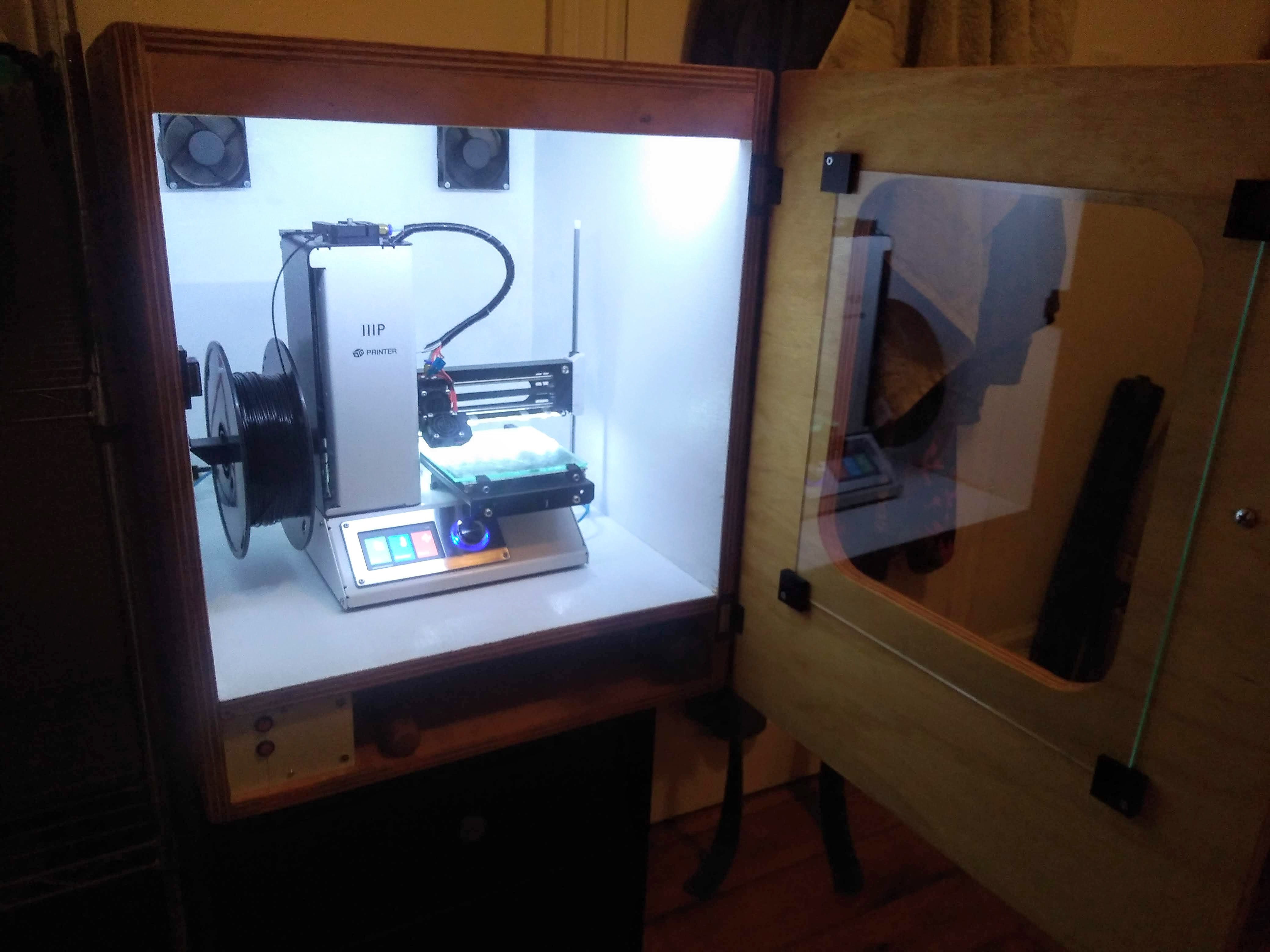
After moving the MPSM to the bedroom adjacent to ours, it became impossible to print while sleeping, it just made too much noise. I decided it was high time I came up with an enclosure for the machine. Luckily I had all of the tools and hardware I needed. I just needed to get my hands on a piece of plywood from Home Hardware. I grabbed a nice 4×8 sheet of project panel which was more than enough for this cabinet. I wanted to make sure that there was plenty of space below to store any extra pieces of hardware or tools and that there was plenty of lighting to ensure that I could see what was happening in the cabinet.
I started by producing a rough wooden box with the plywood. Unfortunately I didn’t have access to the table saw at the time, so I was stuck using the circular saw. It was nothing that a quick pass with the belt sander couldn’t handle (Thanks Peterborough Tool Library!). The door was quickly cut with a jigsaw and attached using some cheap hinges from the hardware store. I also cut two holes in the back to place some fans for controlled ventilation.
Here they are simply installed in the front.
The electronics all came together smoothly, and I even had most of the parts I needed lying around. I used a small 12v 5a power supply for the LEDs and the fans. It was all wired together using a small piece of breadboard and controlled by some red push buttons I had lying around. All of the electronics fit in a small space in the base of the cabinet.
 I wanted it to be very bright inside the cabinet, so I painted the inside with some high gloss white paint. I stained the outside of the cabinet with some oil. I even had some helpers come by for this part of the project! After it had all dried, I placed the electronics back in place and reattached the hardware. I used a small piece of 1/8 inch glass attached with some hardware corner brackets printed on the 3D printer. The extra space in the bottom also houses a raspberry pi that I run octoprint on. With the printer in place it is time for a test print. Next up I would like to run my webcam into the enclosure to be able to monitor my prints remotely. I’ll keep you updated with some slick videos produced in the cube!
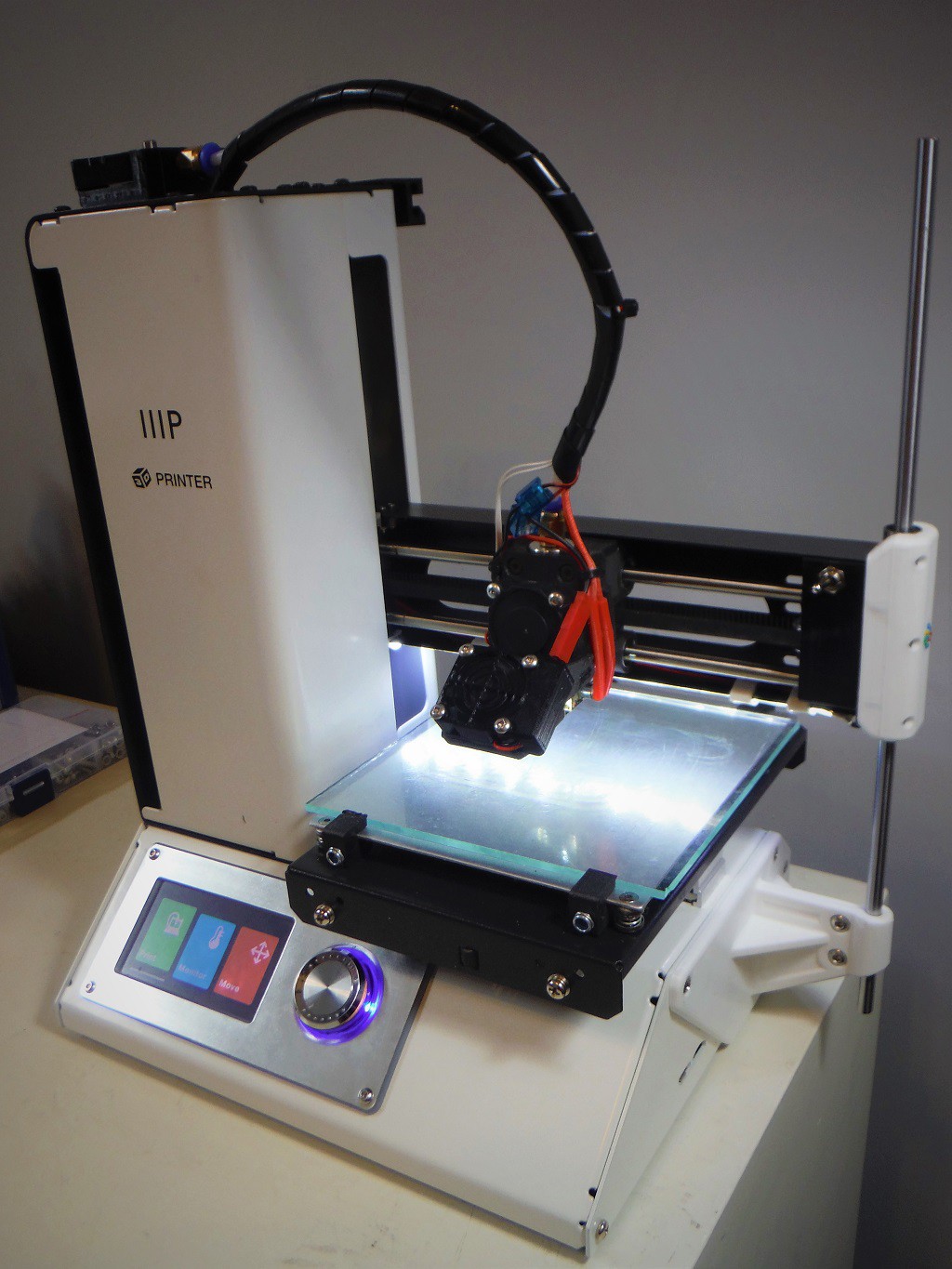
There are several Z axis support downloads that exist for the Monoprice Select Mini printer. After I noticed some wobble on my printer, I wanted to see if a Z axis stabilizer could fix things up for me. Unfortunately I wasn’t a fan of most of the designs that were available on Thingiverse. Several of the attachments for the end of the gantry were bulky and diddn’t actually align with the Z axis rods. The attachments to the side panel were bulky and didn’t necessarily fit with the other modifications that I had completed on the printer. So I set about to design a mod that fixed all these problems.
The modification is relatively simple. 6 M2 x 8 screws are used to clamp 2 LM6LUU bearings to the end of the gantry. The clamp is attached to the gantry by the two screws that are already included with the MPSM V2. If desired you can attach the colour details in any arrangement you desire.
Colour Details are carefully added with tweesers and a dot of superglue
You can then attach the gantry arm in place using the screws that are already on the side panel a 30mm x 6mm rod and 2 x M3 screws as pictured above. If desired you can print a cap to the rod for aesthetics.
In all this is a relatively simple modification that takes less than 15 minutes to install as soon as you have all of the required materials. I can guarantee that you will see an improvement in print quality. Plus I think it looks pretty cool too!
The Monoprice Select Mini has become the workhorse of my 3D printing and making projects since I acquired it in the fall. I haven’t had many complaints while using it, but one issue that I felt needed to be addressed was the dark build plate. Obstructed by the gantry and the print head, it is very difficult to see what is happening on the print surface and make adjustments to bed height or monitor any issues that may be occurring within the print itself. In order to fix this issue I decided to wire up an LED strip to the gantry assembly. Since I don’t always require an LED strip running on the printer, I wanted to include a switch to control the light in an easy to reach location.
You can download the files to complete this modification free of charge from our store page.
Materials and Equipment List:
You’ll need to start this whole process with some disassembly, I suggest moving the gantry up about 50mm – 100mm from the build plate in order to make life easy. Remove the bottom plate, the front and back tower plates, and the gantry support. Disassemble the end of the gantry and replace the end bracket with the one you have printed. If you’re having trouble taking the stock bracket off, be patient a few quick taps with a wooden block should work just fine.
Cut the LED strip to the desired length making sure to cut in the appropriate location. I was able to cut mine to include 12 LEDs total. Remove the adhesive strip from the LEDs and attach it to the bottom of the gantry. Solder about 7cm of wire between the positive pad on the LED strip, and the toggle switch. Next, measure out enough wire to stretch from the end of the gantry to just beyond the stepper motor driving the x axis. Solder the positive wire to the toggle switch and the negative wire to the negative pad on the LED strip. You will notice on the gantry that there is a slight gap in the bottom corner where it is possible to very nearly push a wire into the slot. Using your metal cutting tool of choice (dremel or hacksaw), widen the gap by a couple of millimeters and push the wire into place. If the wire is a little snug, that is ok, it will help it hold in place.
Using the printed clips you are now ready to fix the wires and the LED strip into place. Leaving some slack on the end with the toggle switch, add each clip about 20-40mm apart. I found that placing the wire into the clip and then attaching it to the gantry over the LED strip worked well. Once the clips are attached and the wires secured, place the toggle switch into the empty hole on the printed end bracket and secure it in place. Reassemble the rest of the gantry ensuring that all of the wires are tight under the clips. There should be a couple of centimeters of wire protruding past the stepper motor inside the tower.
Next you will need to run a wire from the main power supply and up the tower to where the wires you installed are hanging. In order to get the correct length of wire, I started by soldering a terminal into the end of the wire before even cutting it. I removed all of the zipties from the wire bundles inside the machine. Still connected to the spool I ran the wire up from the bottom of the machine to where it could connect with the loose wires hanging from the gantry. Working from the top down, I re-bundled all of the wires together with zipties incorporating the wire that I have added to the bundle. Once I had reached the base of the tower, I flipped over the machine and cut the wire in the base, leaving myself about 25cm of wire to play with. I directly soldered the wire to the bottom of the positive and negative terminal on the circuit board....
Read more »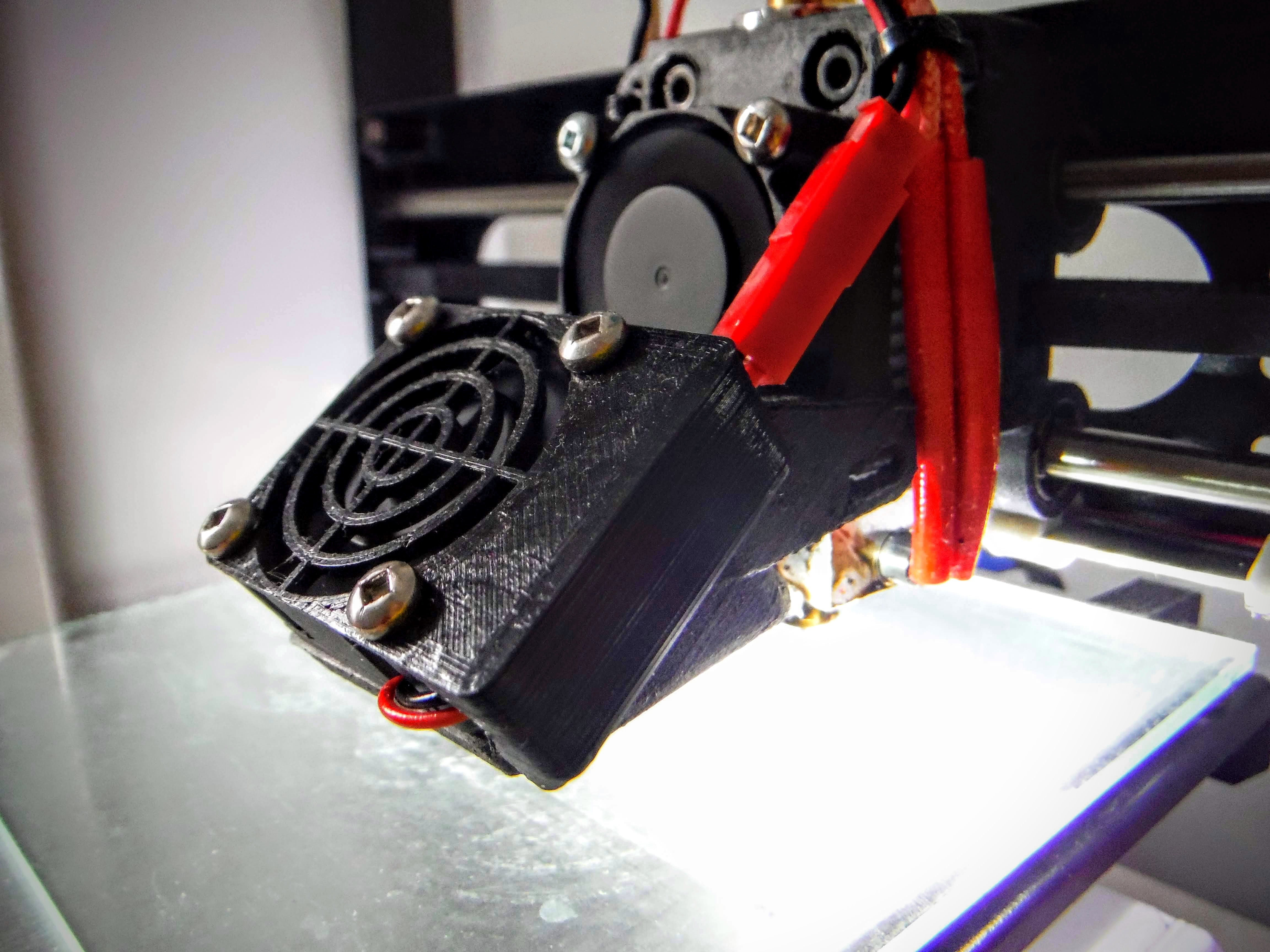
After printing out a couple of benchmarks with the upgraded carriage and cooling fan modification I’d noticed that overhangs facing away from the printer were not what I was hoping they would be. I suspected a first candidate for fixing the problem would be to pull the small circuit board out of the fan shroud. I had initially hoped that the board would be tucked away and small enough to not impact print quality; I was wrong. The problem became where to put the board. I was not interested in a complete rewire of the project so I needed a better solution.
Half of an hour in CAD and this is what I came up with. I’d always planned on putting a small fan shroud on each of the cooling fans, why not integrate a small space for the circuit board to tuck it all away? Perhaps I’ll add space for a small button to control the fan without unplugging it.
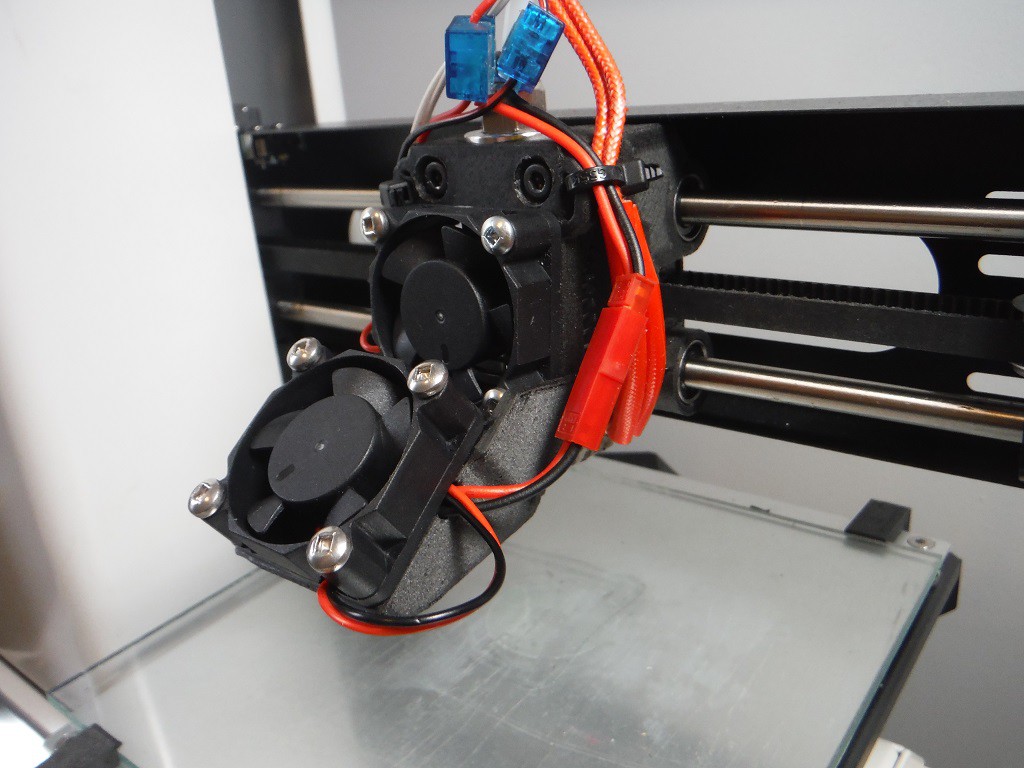
Over the past several months I’ve been working with the Monoprice Select Mini V2 it is a solid printer right out of the box especially for the price. Despite all of the amazing things about this printer, it does come with a couple of small flaws, many of which can be fixed for pennies with a simple print and some cheap hardware. Today I’m looking at the E3Dv6 carriage upgrade by US Water Rockets. As a bonus I’ve included a short guide on how to effectively wire the LED and part cooling fan that is meant to be attached to this modification.
I’d had my eye on this upgrade soon after picking up this printer. I’d noticed that the stock carriage for the E3Dv6 style extruder that comes with the printer causes the gantry to tilt ever so slightly forwards as the center of gravity is quite far away from the linear rails. Additionally, printing calibration cubes demonstrated that the printer had a fair amount of play in the x axis. Initially in order to fix this I had printed some belt tensioners also designed by US Water Rockets. However, this carriage design improves the belt tensioning system dramatically by integrating it directly into the carriage.
This upgrade was also an opportunity to upgrade the stock plastic GT2 pulleys with full metal ones (Shout out to spool3d.ca). The part cooling fan is the only part of this print where I could see there being room for improvement, the rest of this upgrade is rock solid and really made a measurable improvement in the printer’s accuracy.
US Water Rockets already has a great set of instructions on hackaday.io so I’ll just be adding my notes to their already comprehensive instructions.
In order to ensure the longevity of this part, I would encourage anyone printing it to use carbon fiber filled PETG. I used ColorFabb XT-CF20 to print all of the parts pictured here, remember you will need a steel hardened nozzle to print with this filament.
All parts for this upgrade were printed using carbon fiber filled PETG.
Stumbling Points:
The printer ready for its upgrade. I ended up using the stock E3Dv6 style extruder instead of the one pictured in the printed carriage.
The hackaday article did not cover in any detail how to install the part cooling fan and there seemed to be a lot of questions around the internet, but no solid answers.
Parts Needed:
Start by using the cold wire spices to attach a female plug to the positive and negative wires on the existing 12v fan. You don’t need to use a cold wire splice, as it is possible to solder the wires together, but this make the process pretty quick and painless.
Wiring for the breadboard. Not pictured are the connections for the fan or negative wires for the LEDs.
Next up, take a 2 x 8 piece of perfboard and attach the positive and negative connections to one end of the board. Having a helping hand really makes this process significantly easier. Solder in place the 100k resistor and a pair...
Read more »Over the past several months I’ve been working with the Monoprice Select Mini V2 it is a solid printer right out of the box especially for the price. Despite all of the amazing things about this printer, it does come with a couple of small flaws, many of which can be fixed for pennies with a simple print and some cheap hardware. Today we’ll look at the glass bed upgrade.
There are a plethora of upgrades that can be found on thingiverse.com for this printer, which is a testament to the incredible community around it. Not all mods are created equal, and I’ll be going over a couple of the ones that I’ve settled on to fix some of the common issues.
First up is a glass bed upgrade. The stock build plate on the mini has great bed adhesion, however the aluminum bed has a tendency to warp and deform in funny ways, especially at higher bed temperatures. It very quickly got so bad on my printer that it became apparent that it needed to be fixed. Using alligator clips and a glass bed was a quick and easy temporary solution to the problem, however the clearance of the z axis gantry was not enough to make this a long term fix as they severely reduced the size of the Y axis and had a tendency to come loose as the build surface moved back and forth.
I explored a couple of printable solutions to the problem and I settled on ntdesign’s glass bedclips. These bedclips get around the problem of shifting on the Y axis, as many other solutions rely on spring power to force the bed into position which still allows a slight amount of play in the y-axis. With this mod the glass build plate is rock solid and has virtually no play. There are two downsides to this mod that I decided I could live with. First, the bed is difficult to remove once installed, I rarely remove the bed, so this wasn’t an issue. Second you need to be fairly precise when cutting the glass bed, if you cut the glass a little two small, it will allow the plate to shift while printing.
Materials You Need:
I’d recommend as with many mods you start by moving the Z axis gantry to a higher position. Start by removing the build tack surface on the mini to reveal the aluminum surface. You will likely need to use some goo gone to completely clean the surface. Once you get it to the point as it appears below you can install the parts.
Place the threaded rods below the bed and install them on the front bed clips. Be sure to install the nylock nuts on the outside face of the clips. Loosely place the back brackets on the threaded rods and place the glass bed in place. Tighten the entire assembly together and it should appear as in the above picture.
The glass bed is rock solid and I have been using it for a couple months now. The absence of any play in the build surface means parts come out with a bit less Z layer banding than on many of the other bed clip options. Additionally the bed rarely requires any adjustments to its height. A quick spritz of hairspray once every so often will keep this bed printing rock solid parts. Once you have the bed in place you can truly press start and leave it be. Next up we’ll look at the E3Dv6 extruder carriage designed by U.S Water Rockets.
Create an account to leave a comment. Already have an account? Log In.
Become a member to follow this project and never miss any updates