 Ben Jacobs
Description
The Preamplifier Subsystem is, in practice, actually a buffer circuit. It was originally designed to boost the incoming electric guitar signal to line level, but it was found that the WM8731 Audio Codec had a sufficiently high-quality preamplifier built in. Thus, all that was needed was a buffer circuit, to mitigate impedance differences between the Audio Codec input and the electric guitar pickups. A buffer circuit does not amplify a signal, but it prevents the input signal from being overloaded by isolating it from the output (the load). This is accomplished using an OPAMP with unity gain.
Schematic Diagram
Below is a schematic diagram for the preamp/buffer circuit being used. It was designed by team member Ryan Knepel, and serves as a buffer between the electric guitar output and the guitar pedal input.
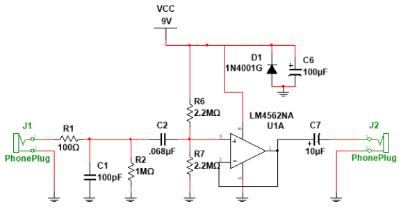
In the schematic above, take note of the following components and their purposes:
- R1 and C1 are for noise.
- C2 is a decoupling capacitor.
- R2 is intended to prevent pops from switching the circuit on.
- D1 is to protect against reversed polarity.
- C6 is for power supply filtering.
- C7 is to ensure an AC output.
- R6 and R7 provide the power supply voltage divider.
Implementation
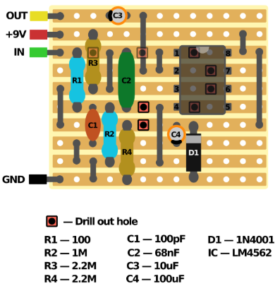
The physical implementation of the preamp circuit was built using perforated PCB material and through hole components. A strip-board layout image may be found below:
Discussions
Become a Hackaday.io Member
Create an account to leave a comment. Already have an account? Log In.