 Ben Jacobs
Description
The Power Supply Subsystem, assigned to team member Katarina Ochoa, provides power to all the hardware components in the Pedal. It consists of two buck-boost regulator modules: one for 3.3V output and one for 5V output. Both are rated for a maximum current load of 3 Amps, and they take their unregulated input voltage from a 9 to 12V DC wall adapter.
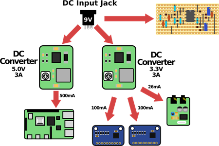
Block Diagram
The following block diagram shows how the Power Supply Subsystem distributes power to each of the main hardware components. From left to right, the Raspberry Pi is powered from the 5V regulator, and the ADC boards and Audio Codec take their power from the 3.3V adapter. The Preamp Circuit takes power directly from the DC jack for maximum audio headroom. The current draw values listed on this diagram are estimates from initial testing- be cautious and verify these values for yourself, because newer Raspberry Pi models usually draw more current
Component Selection
The power supply modules themselves were purchased instead of designed to save time and cost. They are generic buck-boost modules from an online retailer, although any low noise, high efficiency regulator circuit would work. The 3.3V module may be found here: Amazon
Issues Encountered
The only issue that was encountered with these power supply modules was the fact that they introduced noise into the audio chain, due to their switching nature. This was mitigated by installing 470uF capacitors across the output lines of each module to smooth out the DC waveform and suppress any emissions. See the section on Building a Hardware Prototype for more information, and a schematic diagram, as this issue was dealt with during that stage of the project.
Discussions
Become a Hackaday.io Member
Create an account to leave a comment. Already have an account? Log In.