It's certainly been awhile from my last project log to now but I assure you there has been quite a lot of progress on the project since the last log. The next project log's with being you up to speed.
High-P Core & Dev Interface PWA:

What was my setup for firmware development and testing?
Most of the modules use the same elements for testing which are the following:
- Digital Discovery Signal Analyser+ leads
- STLINK V3 Mini
Unlike the ST-LinkV2 the V3 features Virtual COM port (VCP) specific features:
- 3 to 3.6 V application voltage support on the UART interface and 5 V tolerant inputs
- VCP frequency up to 15 MHz
- Available on STDC14 debug connector (Which is designed to the High-P Core)
This is very handy to quickly send out serial data for fast debugging. This also saves desk space as you don't to use another tool namely a RS232 to USB cable. As the debugger is using interfacing via JTAG will still have the opportunity to look a specific registers while debugging.
Initial Test Results:
Fail: No 3.3V supply at the High-P Core.
Cause of Failure:
Misalignment of Regulator "REG1" not that you can tell from looking at the board. For this we need to look at the layout.

Just to given you some perspective each pad in 0.25mmX0.45mm with a pitch spacing of 0.5mm. Given the very small pads it's easy to have connection issues when using solder paste and a stencil and placing components by hand or by SMD parts stencils. This IC is ideally suited for PnP placement.
Short Term Solution:
Due to the looming deadline of this contest we had no time a re-spin a new PWA to solve this problem. The short term solution was to remove "REG1" and wire in R-783.3-0.5 Switching regulator module to convert the USB 5V to a usage system voltage of 3.3V. This fixed the issue and allowed us to continue development.
Permanent Solution:
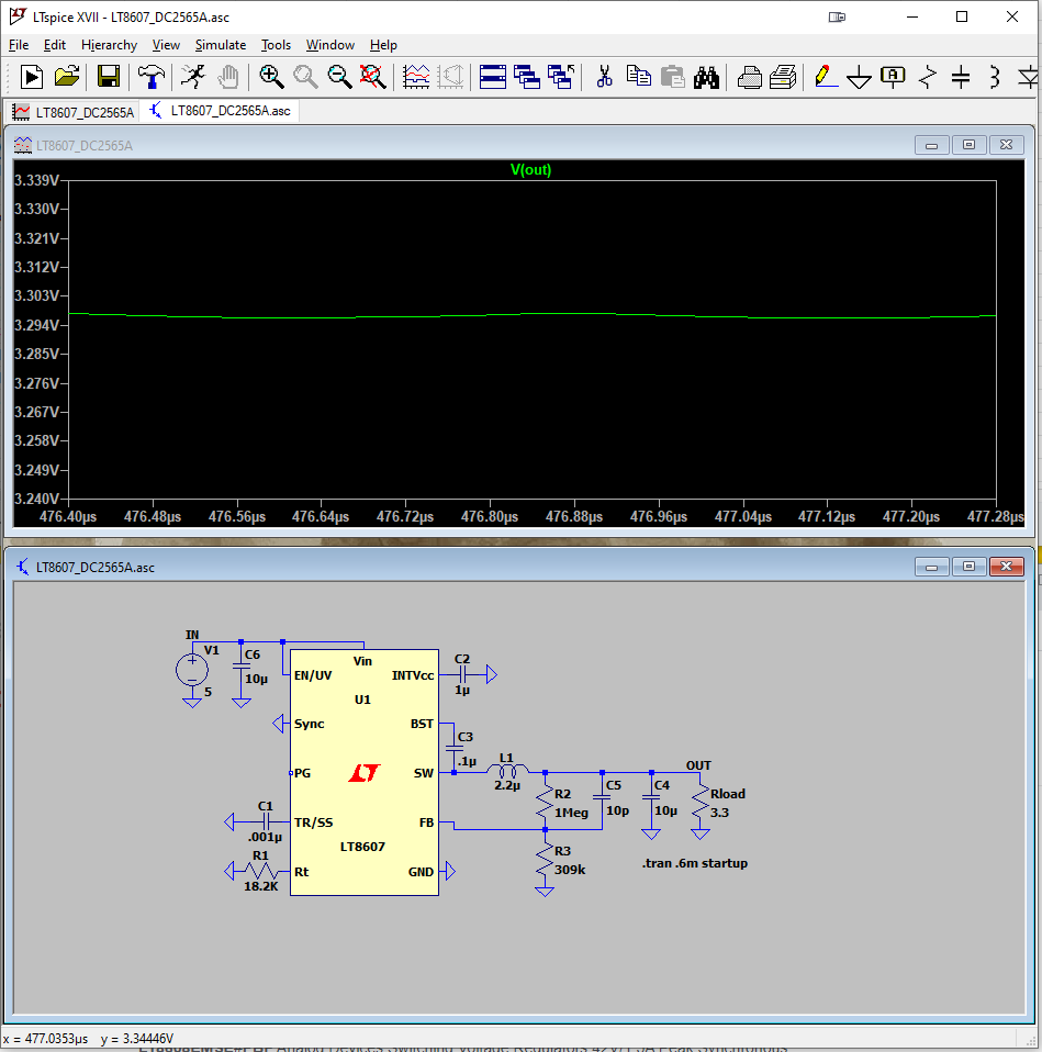
With the short solution sorted I had a few 30 minutes to sort-out the permanent solution that will be using on the Version 2 Dev Interface PWA and the 'to-be' designed lower cost production Interface PWA. The permanent solution will be departing from the ADP7156ACPZ-3.3-R7 Linear regulator to use the LT8608EMSE#PBF Switch mode regulator. This change increases the energy efficiency and also comes in a friendly 10-Lead Plastic MSOP package. The circuit was simulated using LTspice to monitor and reduce the output ripple.

Luckily for us this was the only fault on the Dev Interface PWA. After that both the High-P Core & Dev Interface PWA continued to worked with no problems. Not bad I must say.
 benw
benw
Discussions
Become a Hackaday.io Member
Create an account to leave a comment. Already have an account? Log In.