-
Preliminary design
04/29/2020 at 16:20 • 0 commentsDigging into the documentation I started to get an idea of the complexity of the design, there's no way around this being a 4-layer design. Along with the dozens of passives and feed-lines required for the RF bits, power and signal lines would have to be routed in amongst it all to control the LoRaWAN RF path switch and LNA for the GPS antenna.
With size being important I started with an outline of the absolute maximum acceptable size and worked within its boundaries to fit everything in. 28mm x 18mm was my starting point.
---------- more ----------All the passive components are 0402's, with a handful of 0201's scattered in there where required. I was planning on hand assembling the first test units, but that might be more hassle than it's worth at this point.
To keep everything tightly packed while maintaining good transmission lines for the RF I had to reduce my standard via hole size from 0.3mm to 0.2mm. This shouldn't cause too much of an issue since 4-layer impedance controlled PCBs are usually made with tighter tolerances and better capabilities than standard cheap 2-layer PCBs anyway.
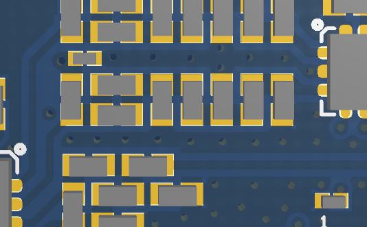
For an idea of how tight for space the layout is, here's a section of the layout. For reference the IC on the right is 2mm x 2mm, and there's about 0.175mm between the passives.
![]()
For the Antenna connections I'm a little torn between two options.
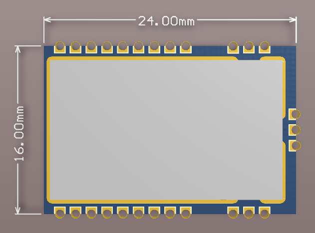
1. The three connections on different edges:
![]()
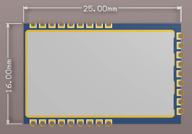
2. All three antenna connections on the far edge
![]()
The first option is slightly smaller, but the second gives a little more space for components and routing and potentially makes routing easier on a carrier PCB. If there are any differences in RF performance I think they're marginal. I'm leaning towards the second option and overall pretty happy with the size of both.
Any thoughts, anyone?
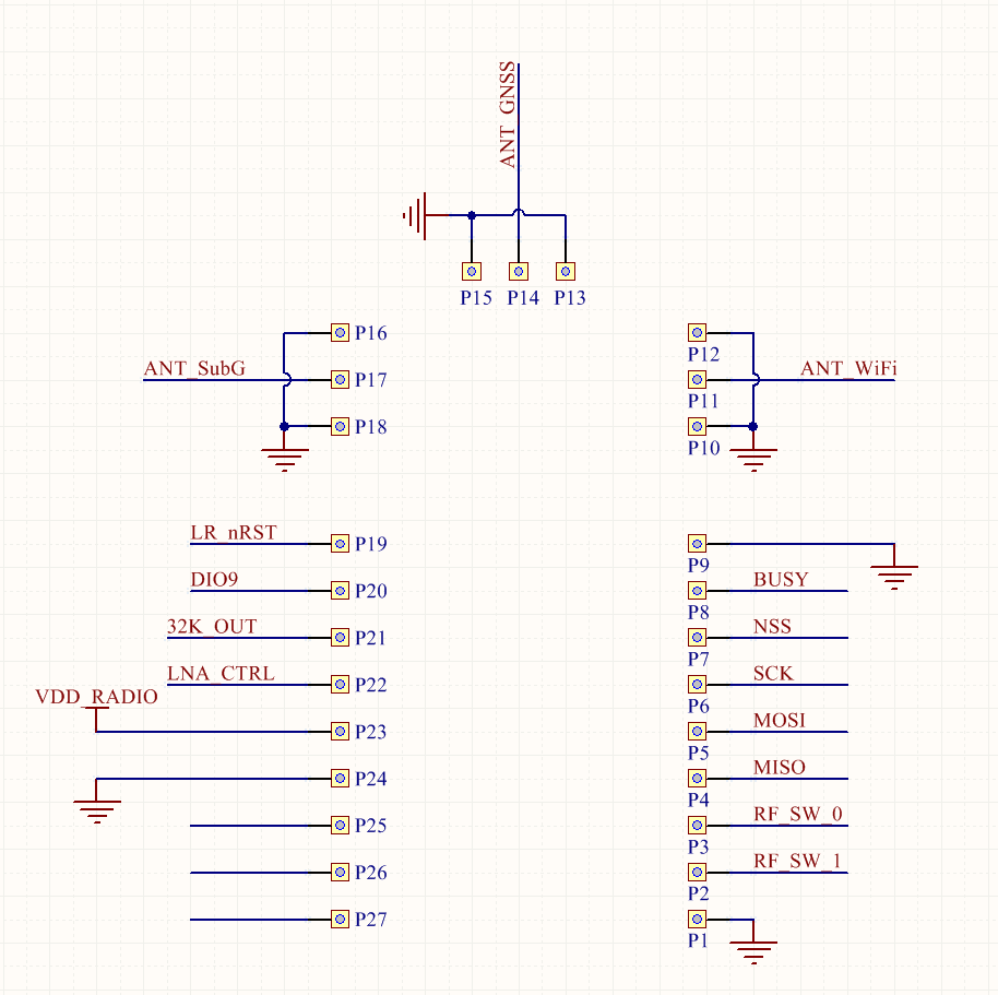
I've still to properly route the control signals to the side connectors. Once I finalise the antenna connector position I'll post an update with the pin labels too. There are a few less important things that I could break out; a 32KHz clock output, and GPIO (like the control line for the GNSS LNA and RF switch which are probably only useful for diagnostic purposes).
This is the pin-out for now, which will definitely change!
-
A Summary of Low-Power Geopositioning
04/28/2020 at 10:53 • 0 commentsThe LM1110 leverages three technologies to have its position determined:
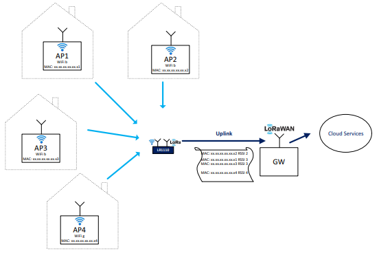
- Wi-Fi Passive Scanning
- GNSS Scanning
- LoRaWAN Geolocation
The important thing to note is that these positioning techniques are only fully (or at all) effective when used in conjunction with an external source of information or service, which imposes a bit of limitation on potential applications.
---------- more ----------Wifi Passive Scanning
The LM1110 is able to discover WiFi b/g/n (2.4GHz) access points available in the vicinity of the device and extract the MAC addresses. By transmitting these addresses to a Wi-Fi lookup service the positioning information can be obtained. The likelihood is that you'll do this via an external server, transmitting the MAC addresses via LoRaWAN.
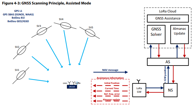
GNSS Scanning
The GNSS scanner of the LM1110 is fast and low-power, capturing a short portion of the GNSS (GPS, BeiDou) satellite signals and extracting the information required to calculate the device position. Again, this information (NAV message) is then packaged up and sent to a back-end system to compute the actual device position. By offloading the time and processor intensive work of resolving the full position, energy-efficient GNSS positioning is made possible.
There are two modes of GNSS scanning that can be used: Autonomous, and Assisted.
Autonomous Scanning
In this mode a fast search of all satellites is carried our, and any with a strong signal (better than -134dBm) are detected.
If no strong signals are detected the device presumes it is indoors and searching for weaker signals, which is more time/energy consuming, can be scrapped. In this case it may be preferable to switch to an alternative mode of positioning (e.g. WiFi scanning) to save power.
Assisted Scanning
In order to improve the efficiency and minimise the search space for satellite signals, assistance parameters can be provided to the device. These parameters include Rough estimate of device position, current time, frequency reference error, and recent version of the GNSS Almanac...
The Almanac parameters contain coarse orbital information which describe the satellites' motion in space. Together with a coarse estimate of time and position, the Almanac can be used to exclude irrelevant space vehicles and reduce the search window for the Doppler error search.
All of these parameters have a contribution to the total error of the Doppler estimation for each satellite.
Based on the information the LR1110 will build a list of 10-12 satellites that is should look for at it's current position and time and then move onto performing the scans.
LoRaWAN geopositioning
Given that the device is intended to be on a LoRaWAN with an accessible network service, aLoRaWAN geolocation positioning/solver service can be used:
Semtech’s LoRa geolocation solution is enabled by version two LoRaWAN gateways that share an accurate, common time base and add an ultra-high resolution timestamp to each received LoRa data packet. Each base station will report the time of arrival and supporting metadata enabling location solvers based on differential time of arrival (DTOA) algorithms to determine the end node position to the nearest block.
In short, transmitting devices positions are triangulated based on the comparison of when the signal arrives at each gateway. A whitepaper by the LoRa Alliance boasts positioning accuracies in the 20m to 200m range.
Conclusion
Overall the LM1110 takes a fairly unique approach to geo-positioning by leveraging multple technologies and infrastuctures, with a lot of neat features to improve accuracy and keep power consumption as low as possible.
However, it's clear from the methods it uses and how it relies heavily on back-end processing that this part is primarily intended for remotely tracking and management assets. While it could potentially be used in a hand-held positioning system (if you returned the positioning information from the back-end), it couldn't be a standalone device.
If you have any thoughts on this, I'd love to hear them!
-
Background
04/27/2020 at 16:40 • 0 commentsI got started on this project a week ago when I found details of the LR1110.
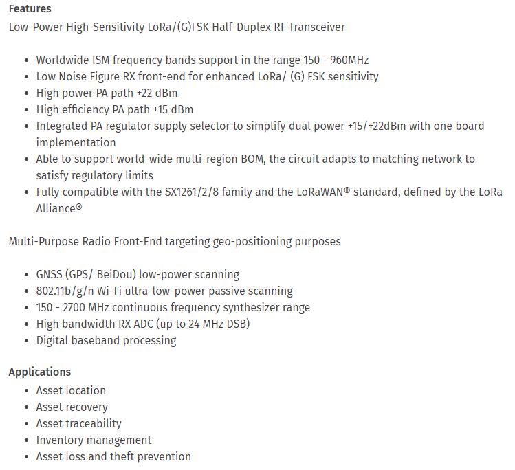
This is what Semtech say about it:
After reading this I started to get excited about the potential... Imagine having a tiny device that can remotely give you meter-accurate location and run on battery for a year or more! This could be used for tracking anything including vehicles and bikes, livestock, pets, valuables, etc.
Allowing myself to get carried away I started reading into the datasheet and reference designs. I decided fairly early that I'd like to make a module with this part, to scratch my itch for hardware design, support a few of my own personal projects, but also make the part much easier to incorporate for anyone else who was interested.
With that in mind I had a few key requirements:
- Tiny: If it can be tiny, why shouldn't it be? My original goal was 24mm x 18mm.
- Easy to solder: It needs to be able to be soldered without reflow. No hidden pads underneath!
- Multi-region: One module to support CN/EU/NA/AU regions
As an extra point, I wanted to avoid including any antennae on this module. To try to fit 3 different antennae or one multi-band antenna on the module would make it fairly large, and on top of that, module antennae are usually pretty difficult to optimise and crap as a result. It provides much more flexibility to allow the user to choose their own antenna setup; this can be as simple as 3 separate SMA connectors for external antennae or as complex as a custom multi-band PCB trace antenna.
The end goal for this project is to have a few modules built that I can tinker with and test for my own projects, and perhaps also make a batch available to the community if there is significant interest!
LR1110 module - Tiny LoRa & WiFi/GNSS positioning
Leveraging the LR1110 to create the smallest geolocation+LoRaWAN combined module for use in tracking.