 Pavel G.
Motor theory and practice
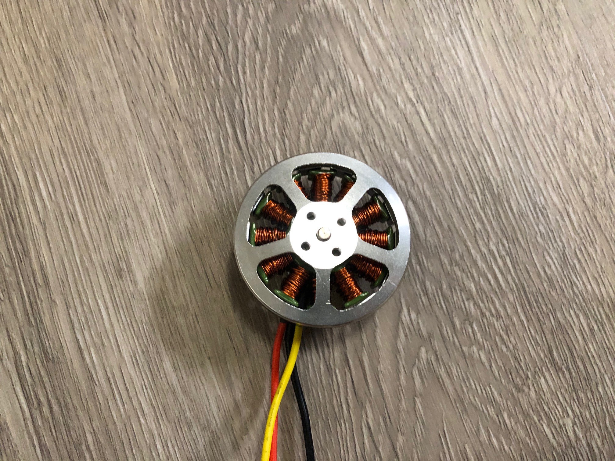
I use brushless 5010 motor rewired as stepper motor with 28 steps per revolution, controlled by L298N module, arduino and 2 hall effect sensors
Image bellow is a 3 phase brushless motor (5010 model) with 14 magnet poles and 12 stator poles, this motor need to be rewired as stepper motor with 28 steps per revolution
Motor wiring diagram (14 magnet poles, 12 stator poles) converted to stepper motor (top view)
NOTE: Arrows lines is always on top of stator lines
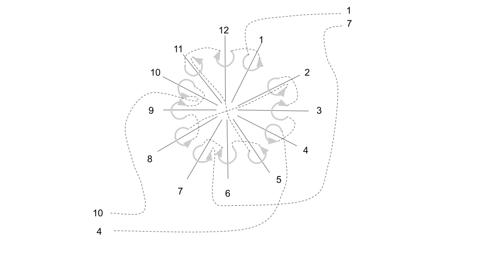
Motor phases animation with wiring above visualized in video bellow
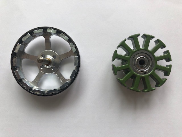
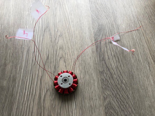
Disassembled motor ready for rewire
I use small radius PTFE tube as a helper for rewiring
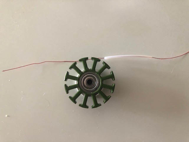
100 turns per pole by 28 AWG wire (very challenging process)
Final resistance 3.7 Ohm per phase
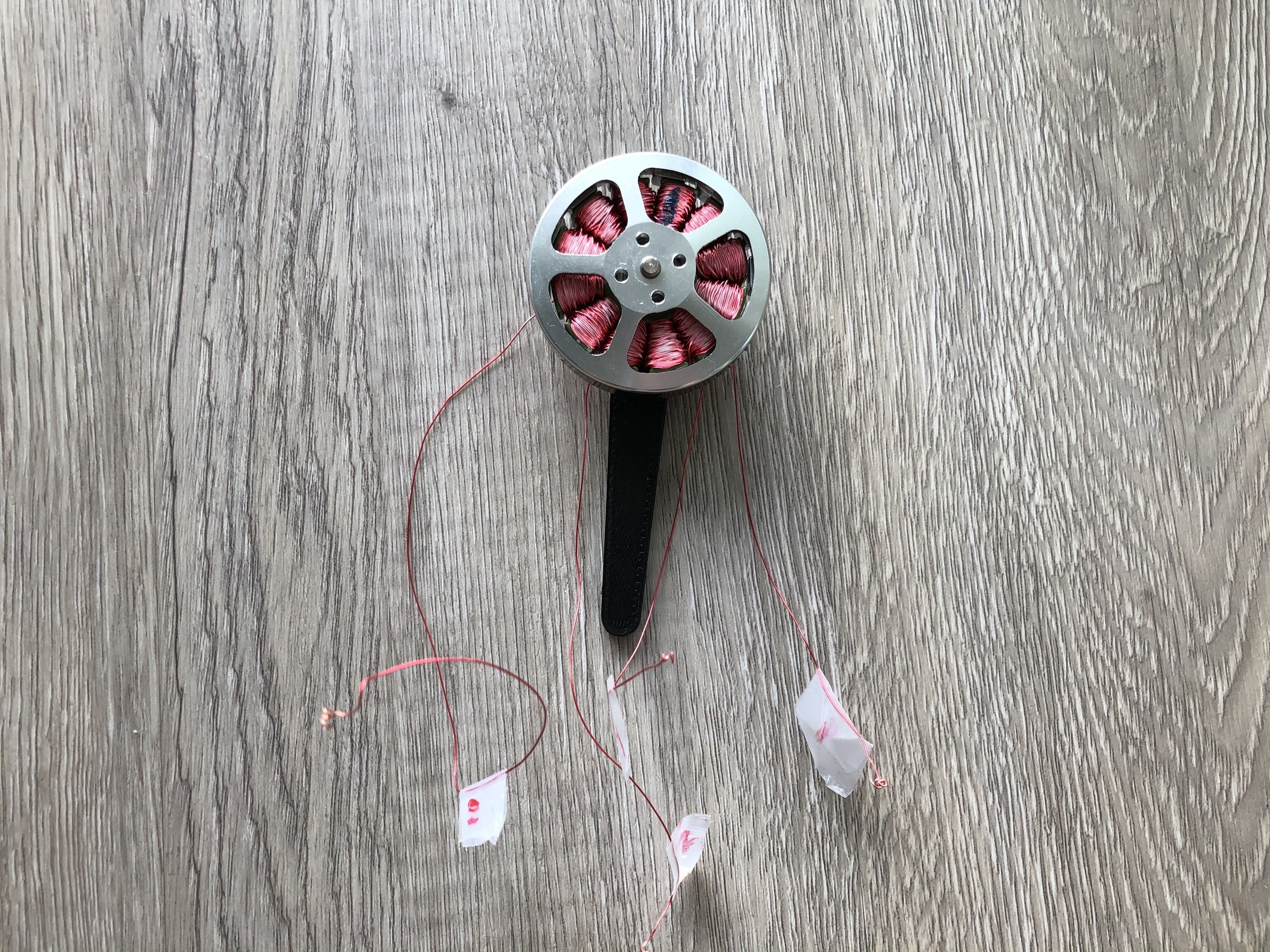
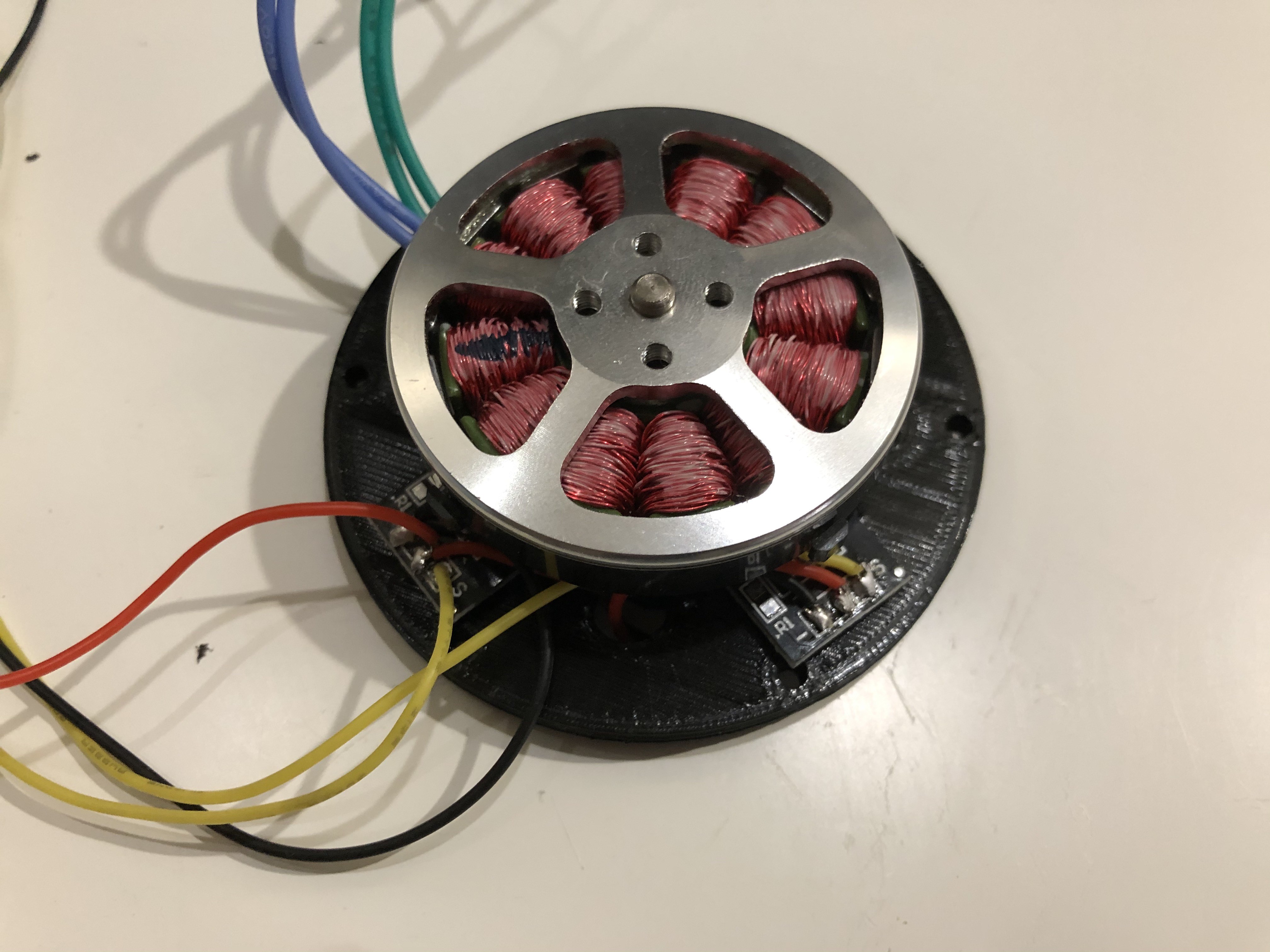
Assembled motor (wires covered by nail polish (pole 1 marked by blue)
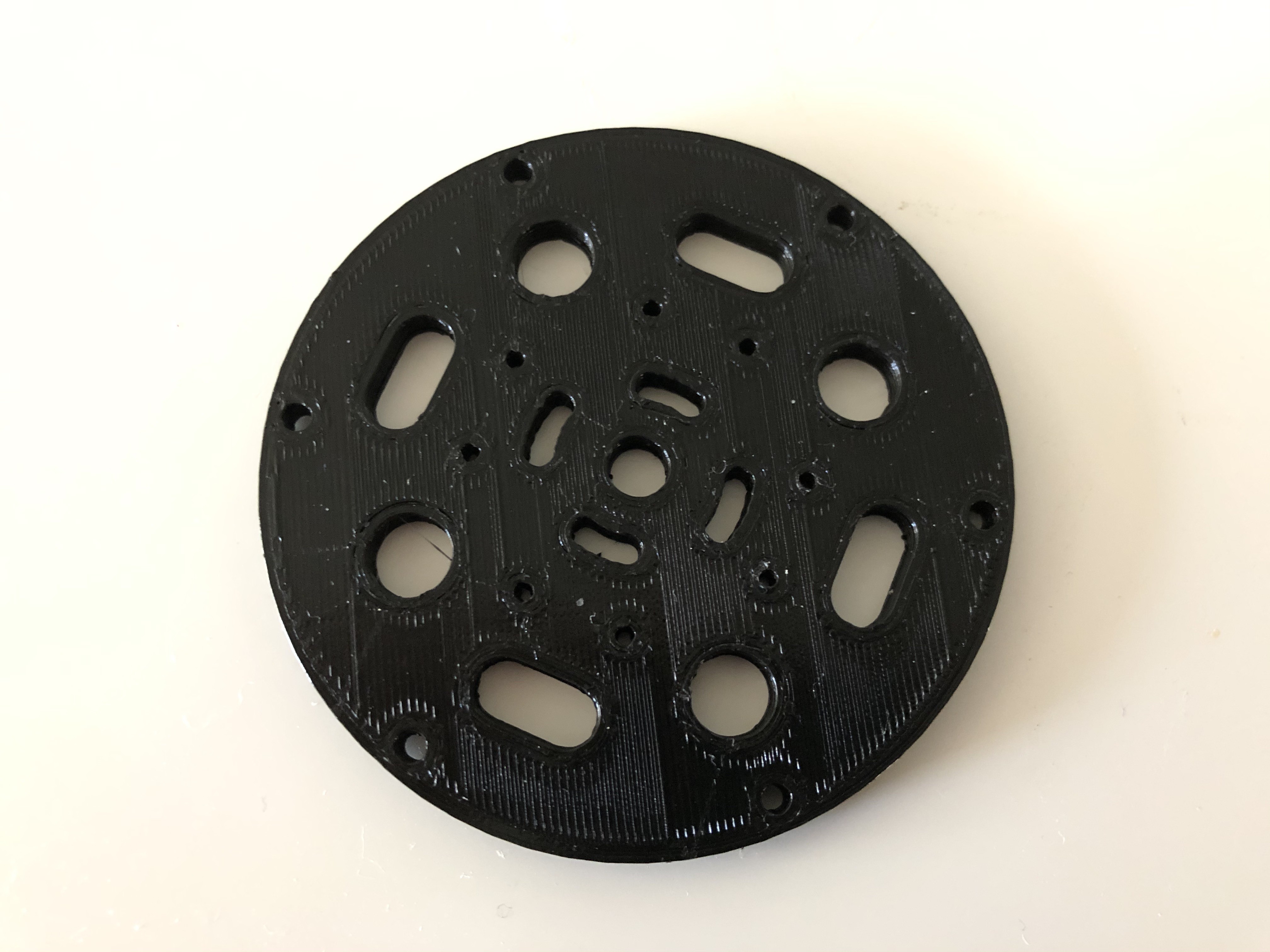
Motor base plate 3d Printed (small holes for hall effects sensors mounting)
2 Hall sensors ready to be mount on base plate (49E 9148G sensor)

Sensors mounted to base
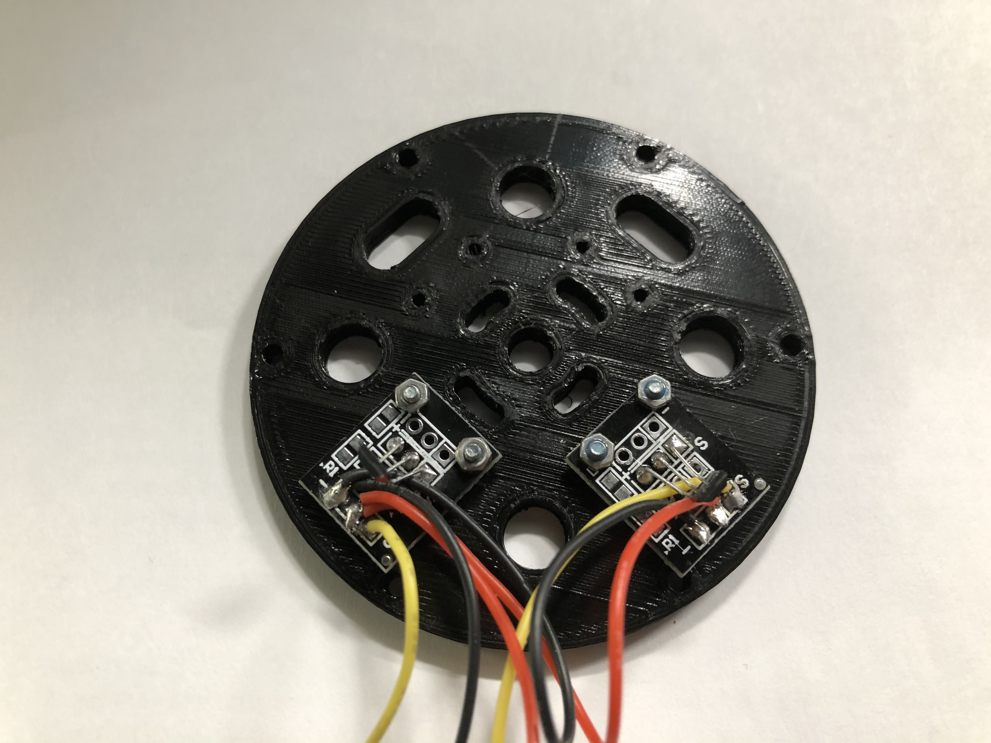
Motor mounted to base plate 1st hall sensor look at stator pole 12 2nd to 9 (it should be 90 degrees)
Sensorless motor test run
Sensored test run
Motor torque test
- 160 PWM - 70g/10cm or 700g/cm
- 255 PWM - 160g/10cm or 1600g/cm
Discussions
Become a Hackaday.io Member
Create an account to leave a comment. Already have an account? Log In.