General
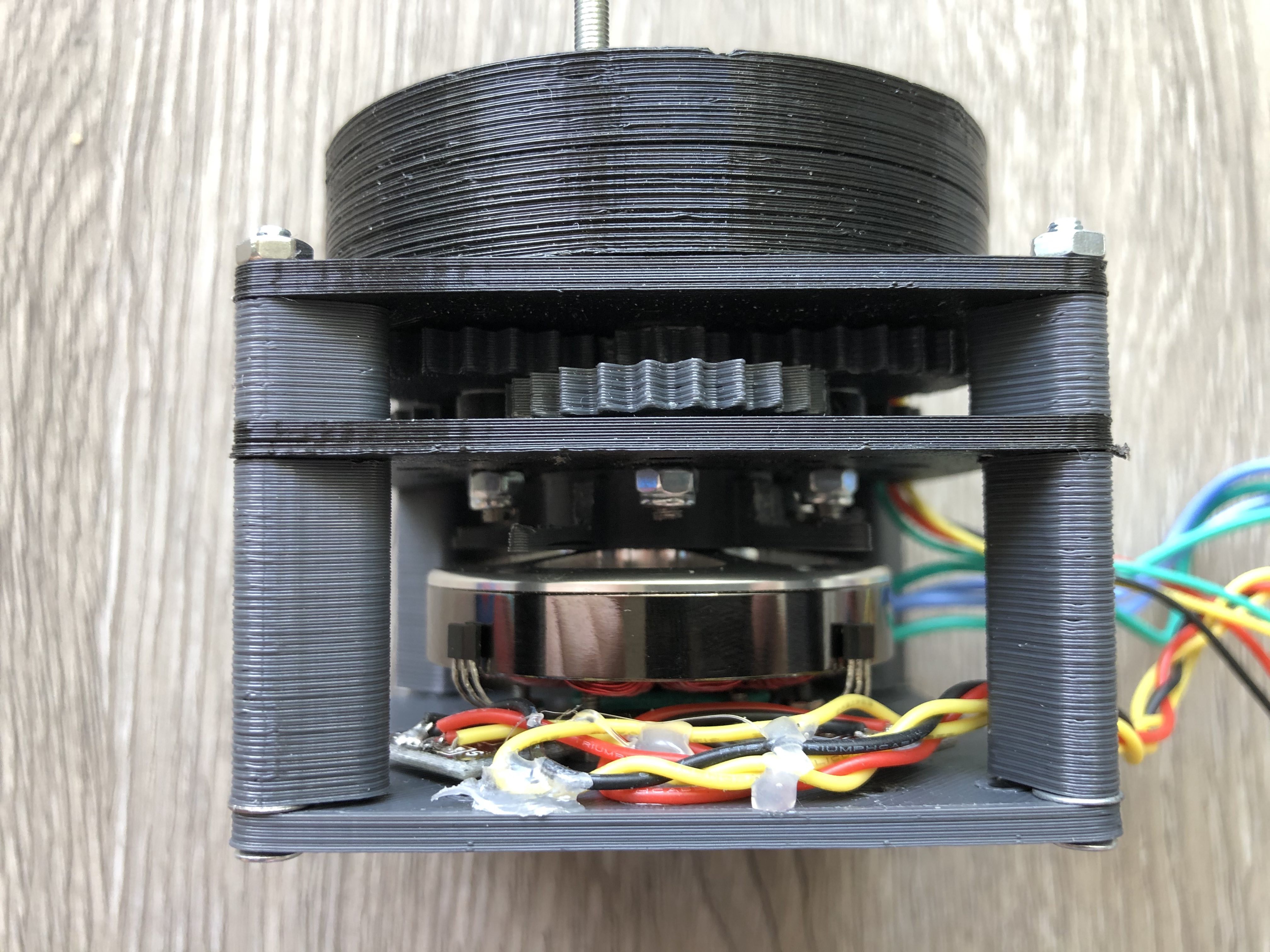
I decided to develop gearbox with ratio from 1:25 to 1:35 to archive 180 degrees per second with full torque (i hope).
Small backlash is acceptable (at least for robot leg actuator)
All designs will be created in Openscad.
Design
I had a few experiments in the past: So my favorite designs are:
1) Spur Pinion double gears organized in 3 gears per stage (each stage is a 3 spur-pinion gears at triangle corners) with ring gear as output: Openscad drawings and visualization will be uploaded soon.
This type of gearbox have 1:33 ratio (can vary, but not limited at max)
2) Cycloidal - i experimented in past, I got 1:25 ratio (strong limit for 70x70 cm footprint), but my past experiments had some Issues (mostly because of missing bearing at critical places)
Best ideas for Cycloidal you can see here:
https://hackaday.io/project/165653-3d-printed-robot-joint-with-active-compliance
https://hackaday.io/project/167855-simple-cycloidal-robot-leg-for-quadruped
Gearbox exploded view concept
Key features:
- Ratio: 1:33.1852 (1st stage 1:2.66, 2nd 1:2.666 output is a 1:4.66)
- Output gears module can be bigger then stage modules
- Gear height can be different for each stage
- Place to embed as5600 i2C absolute rotary sensor (2$ on aliexpress)
- Extra stage can be added without problems (1 extra stage and you can get 1:88 ratio)
- Only output stage is rotate (all double gears are rotates on the static common shafts)
- Each stage have 3 points of contact (less backlash and more torque)
Gearbox disassembly video
Assembled gearbox

Actuator test without absolute encoder
Gearbox test with absolute encoder
 Pavel G.
Discussions
Become a Hackaday.io Member
Create an account to leave a comment. Already have an account? Log In.