The DM-02 (pronounced: “Dee Em Zero Two”) is an 8-bit computer built (almost) entirely out of 7400-series (TTL) logic chips. It is the successor to my 74xx Computer which from now on shall be refered to as DM-01.
Why is there a successor to the DM-01? Well, the main reason is that the DM-01 never got to be a fully functional computer. It worked in Logisim, but due to poor design from my end the actual electronics failed to function properly.
The DM-01 was the first computer I designed all by myself and I was learning how to do it while I was doing it. So naturally, mistakes have been made!
I’ve done quite a bit of research since then and decided to give it another go.
Instead of trying to fix the DM-01, I’ve taking all the lessons learned from my first attempt and start from the ground up.
Please refer to the GitHub repository for all the details and the latest updates.
Status as of May 12th, 2020:
- The computer is fully functional in Logisim.
- Microcode language specified and all microcode has been written.
- Microcode compiler is fully functonal.
- Assembly language specified.
- Assembler is fully functional.
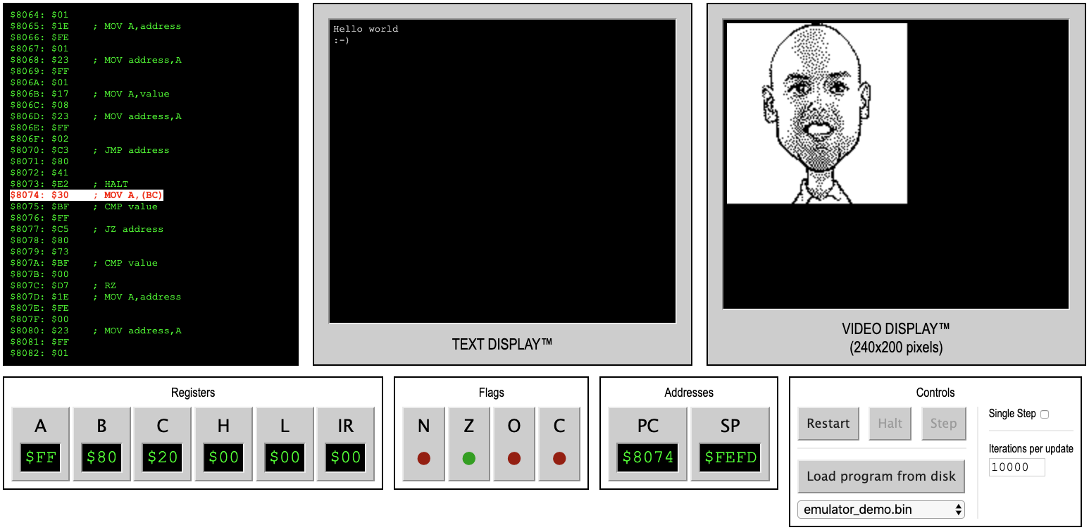
- Emulator is fully functional.
- Basic documentation is in place (work in progress).
- Electronics design is in progress (first couple of PCB's have arrived).
Overall specifications:
- Aiming for a 1 MHz minimum clock speed
- Microcoded control unit
- 8-bit data bus
- 16-bit address bus, allowing for 64 Kb of addressable memory
- 16 Kb reserved for ROM
- 48 Kb reserved for RAM (a 64 Kb RAM chip is used, but only the last 48 Kb can be addressed)
- 16-bit stack pointer (entire RAM may be used as stack space)
- 16-bit program counter
- Register configuration:
- 1x 8-bit accumulator (A)
- 4x 8-bit general purpose registers (B, C, H, L)
- BC and HL may be used as pair for 16-bit operations
- The ALU is based around an EPROM
- Supported flags: Zero, Carry, Negative, Overflow
- Flags can be pushed onto the stack for use with JMP/CALL/RET instructions and for future interrupt support.
- I/O is addressable through memory and there are 256 addresses reserved for this
- Planned I/O modules:
- Program loader (e.g., from SD card)
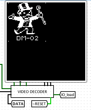
- Graphics card
- Keyboard support
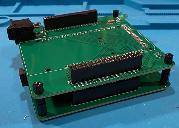
- Modular design based on stackable PCBs
- One of these modules is the Debugger. This board attaches an Arduino Mega to the DM-02 and allows for:
- Running hardware tests against each individual module.
- Simulating the controller module and thus test the interaction between modules.
- Debug the computer while it’s running programs.
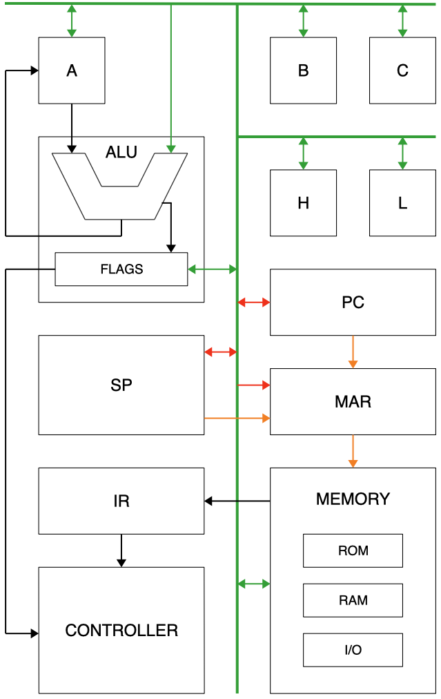
High-level architecture overview
Green lines are 8-bit data bus connections.
Red lines are pairs of 8-bit connections to form a 16-bit value.
Orange lines are 16-bit address lines.
Black lines are internal bus connections.
Read more
For further reading, please refer to the GitHub repository.
 Ruud van Falier

 Nicolas REIMEN
 matseng
 Xark
Xark
Really impressive to see so many quality component and software produced for this project! Especially fascinating is to see another approach at microcode language definition and compiler for it. I written my own and created a number of CPUs/controllers using it: https://hackaday.io/project/172073-microcoding-for-fpgas