 deʃhipu
The PCBs for version 1.2 arrived from @oshpark now, and even though the version 1.3 will arrive tomorrow, I decided to assemble and test it. I used the nice clear soldermask on black FR4 option for the first time, and it does look pretty nice.
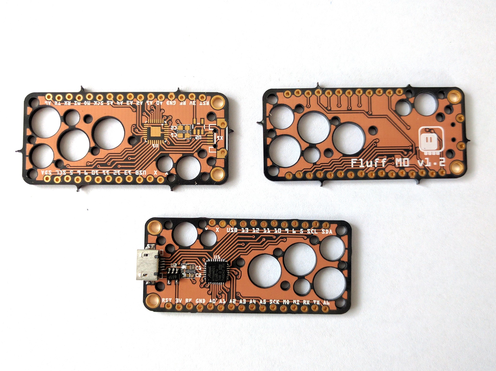
The fix was simple enough, and now the SPI pins are correct and working. The next version will get rid of the micro-USB socket, and use a PCB socket for USB-C — we will see tomorrow how well that works.
Discussions
Become a Hackaday.io Member
Create an account to leave a comment. Already have an account? Log In.