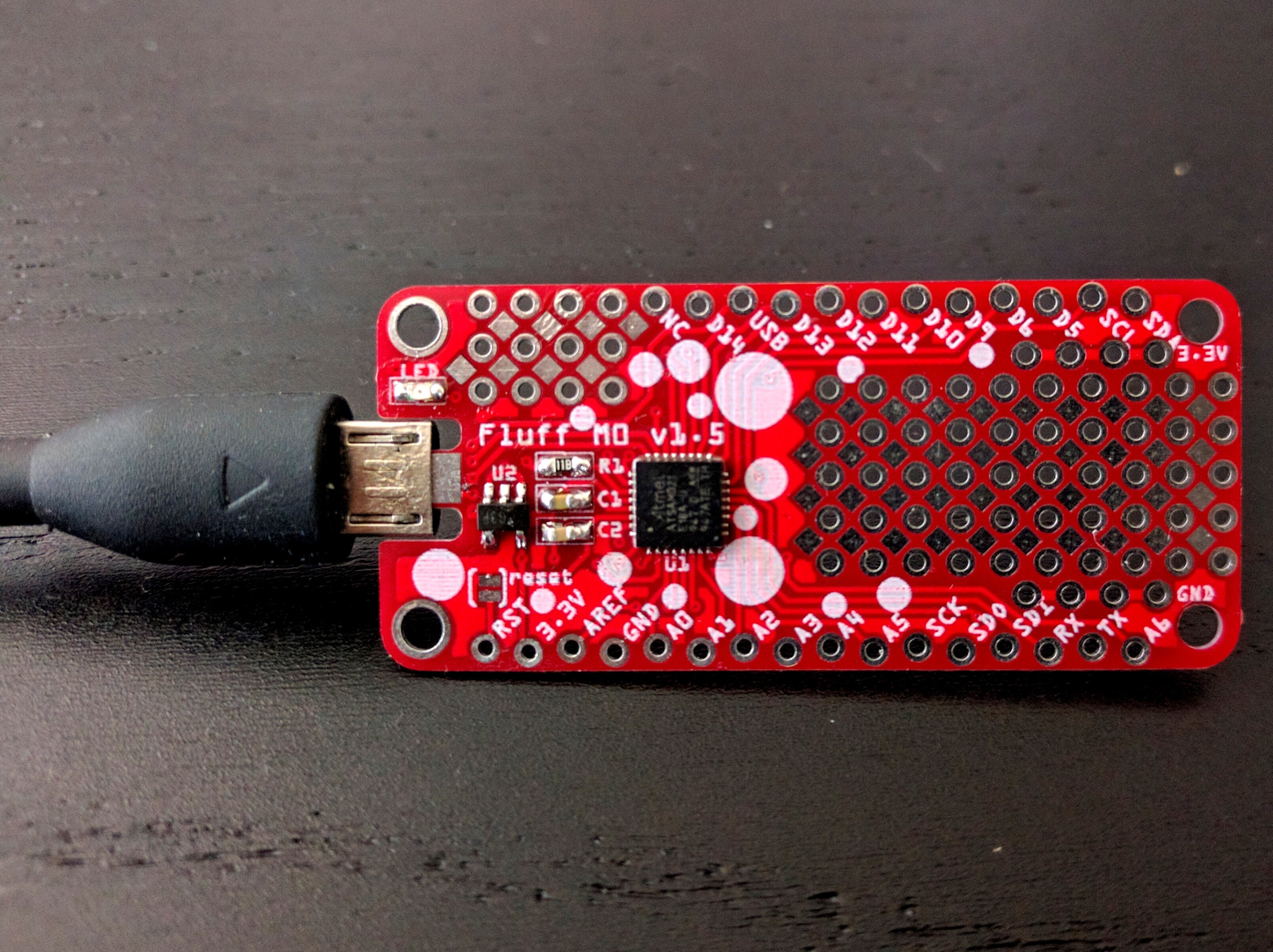
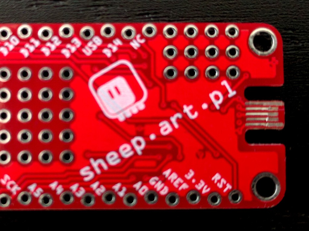
The PCBs for the micro-USB version arrived:

Some notes:
- The connector works. Yay.
- It's a little bit tight thickness-wise. More on that below.
- I made it a little too deep — I can make it about 1.5mm smaller.
- It's strong, even with the vias all lined up like that (later version has the vias more spread). It shouldn't break off.
- There is a bit of sideways wobble possible, but it doesn't seem to cause any connection problems.
- The width of the cutout is just right.
- The pad on the top of the connector, that was supposed to connect to the shield, is useless, and can cause a short if the plug is inserted wrong way around.
- I'm happy with the prototyping areas, I'm going to leave them like that.
- The connector doesn't necessarily look like an USB connector, so I'm going to add a label to it describing it as such.
- The staggering of the contacts, so that power gets connected before the signals, is superfluous, because they are already staggered in the plug. I will remove that.
Now, speaking about the thickness of the connector, it seems to be on the edge of acceptable. The first insertion requires a bit of force and leaves marks on the contacts:

This seems to be mostly to the thickness added by the HASL process of coating the contacts with solder. I hope that removing the pad from the other side will improve the situation here.
Speaking of the board thickness, I also made some 0.8mm PCBs for the USB-C version, and it does sit in the plug much better, while still not being too tight, so that is the preferred thickness for that kind of connector for me.
 deʃhipu
Discussions
Become a Hackaday.io Member
Create an account to leave a comment. Already have an account? Log In.