Next up, I tested all the components under different circumstances to find out 1) under which conditions to operate and 2) if I could possibly replace them.
Photoresistor
I replaced the photoresistor devboard with a standalone photoresistor integrated into a voltage divider circuit. When the photoresistor is "on", its resistance gets very small and most of the voltage drops over the other resistor. If the photoresistor is "off", its resistance gets very large and most of the voltage drops over it. To find out ideal nominal resistor and "on"/"off" thresholds, I tested the resistance under different conditions.
| Condition | Laser 100% intensity | Laser 20% intensity |
| completely dark | 300,000 | 300,000 |
| fully lighted | 20-50 | 120-150 |
| through water tank - below water level | 5,000-10,000 | 5,000-10,000 |
| through water tank - at water level (refraction) | 100-130 | 350-370 |
| through water tank - above water level (air) | 300-500 | 600-800 |
Laser will be operated at 50% intensity at first, but this can be further calibrated. I want to set thresholds for detecting enough water ("on") below 350 Ohms and not enough water ("off") above 1k Ohms. For this, I want to use a nominal resistor of 1k. This way, the voltage thresholds are far enough apart (1.3V and 2.5V respectively) and the resistance is always large enough so only a small current flows (max. 4.5 mA).
| Nominal resistor in Ohms | 330 | 1,000 | 2,000 | 5,000 |
| "on" voltage (% of 5V) | 51% | 26% | 15% | 7% |
| "off" voltage (% of 5V) | 27% | 50% | 33% | 17% |
| difference (% of 5V) | 24% | 24% | 18% | 10% |
| max. I in mA | 12.5 | 4.5 | 2.4 | 1.0 |
Laser LED
When Laser Board is "full on" (5V to GND), 29 mA are measured. This means, the nominal resistor on the board is ~120 Ohms.
With this information, I could rebuild the Laser Board with a standalone Laser LED. I don't have one though and the solder joints on my prebuild board seem sketchy, so I don't want to remove it from there.
In an attempt to reduce energy consumption, I also tried to replace the laser with a normal yellow LED. This light is not focused enough though and the photoresistor won't detect it through the water tank.
RGB LED
I went on to replace the RGB LED board with a standalone 4-end RGB LED and three resistors. I picked 220 Ohms since it is enough to drive the LEDs fully and limits current a little more than the board (150 Ohms).
Power Source
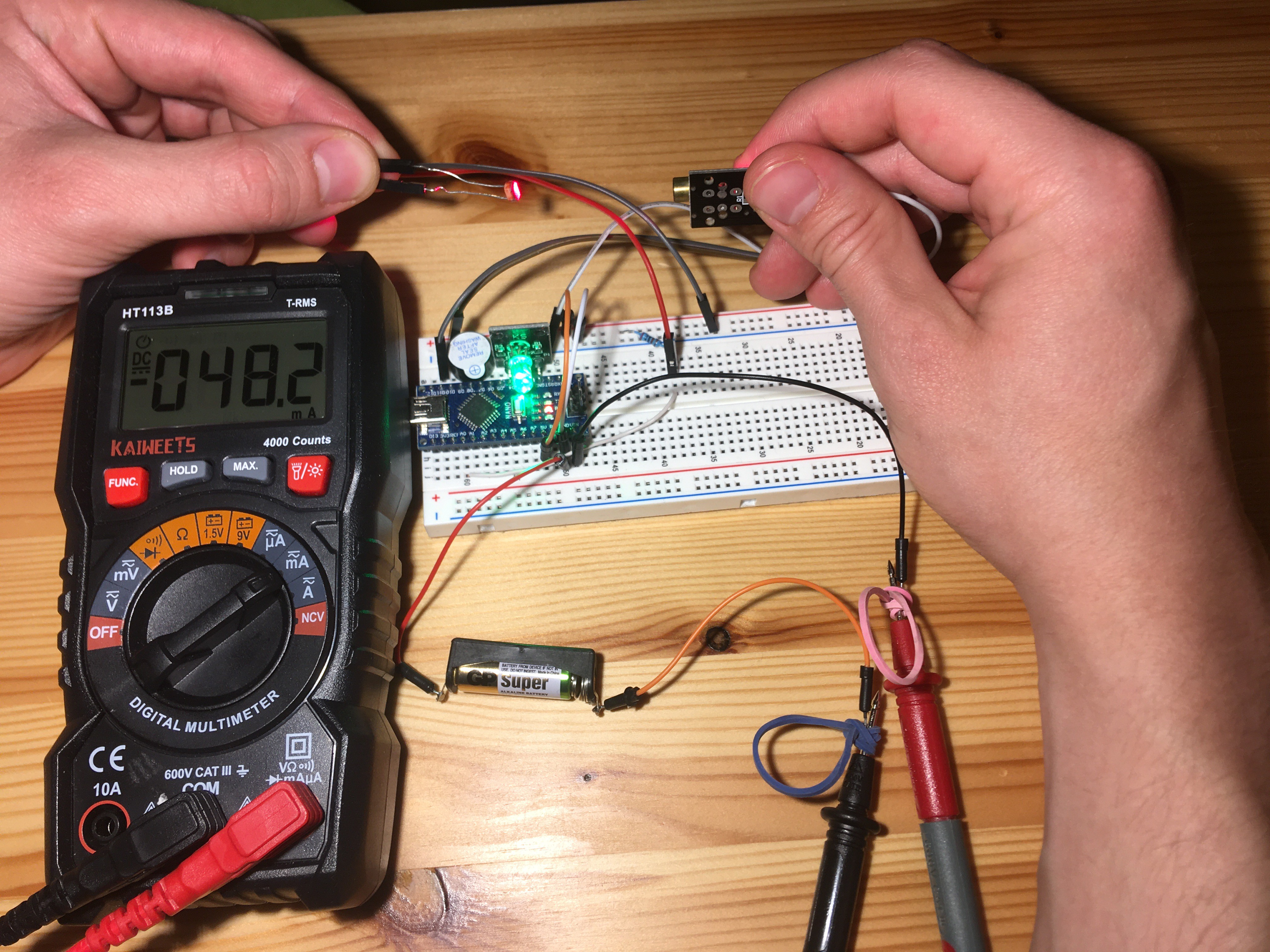
I tested powering the system with a 12V battery via voltage input pin of the Arduino Nano. This worked, but then I tested the power drain: The Arduino pulls 50mA on average. This is well below the max. current of the battery (23 A) but will result in very fast discharge.
The discharge characteristic curve of the battery shows drop below 5V after ~100 hours of discharge with a load of 20k Ohms. The mean voltage during this is 10V, which gives usable energy content of 50mAh. This will power our Arduino only for an hour and even if we can decrease power consumption (don't drive LEDs as hard etc.) will not be feasible. For that reason, I will power the Arduino via Mini USB (wall socket adapter).
Discussions
Become a Hackaday.io Member
Create an account to leave a comment. Already have an account? Log In.